Device for nailing base sheet fasteners

Inactive Publication Date: 2001-04-10
CABRERA PEDRO
View PDF5 Cites 11 Cited by
  • Summary
  • Abstract
  • Description
  • Claims
  • Application Information

AI Technical Summary

Benefits of technology

It is another object of this invention to provide a device that is safe and efficient to operate.
It is yet another object o

Problems solved by technology

There are several nail gun designs in the prior art but to the best of applicant's kno

Method used


Image

  • Device for nailing base sheet fasteners
  • Device for nailing base sheet fasteners
  • Device for nailing base sheet fasteners

Examples


Embodiment Construction

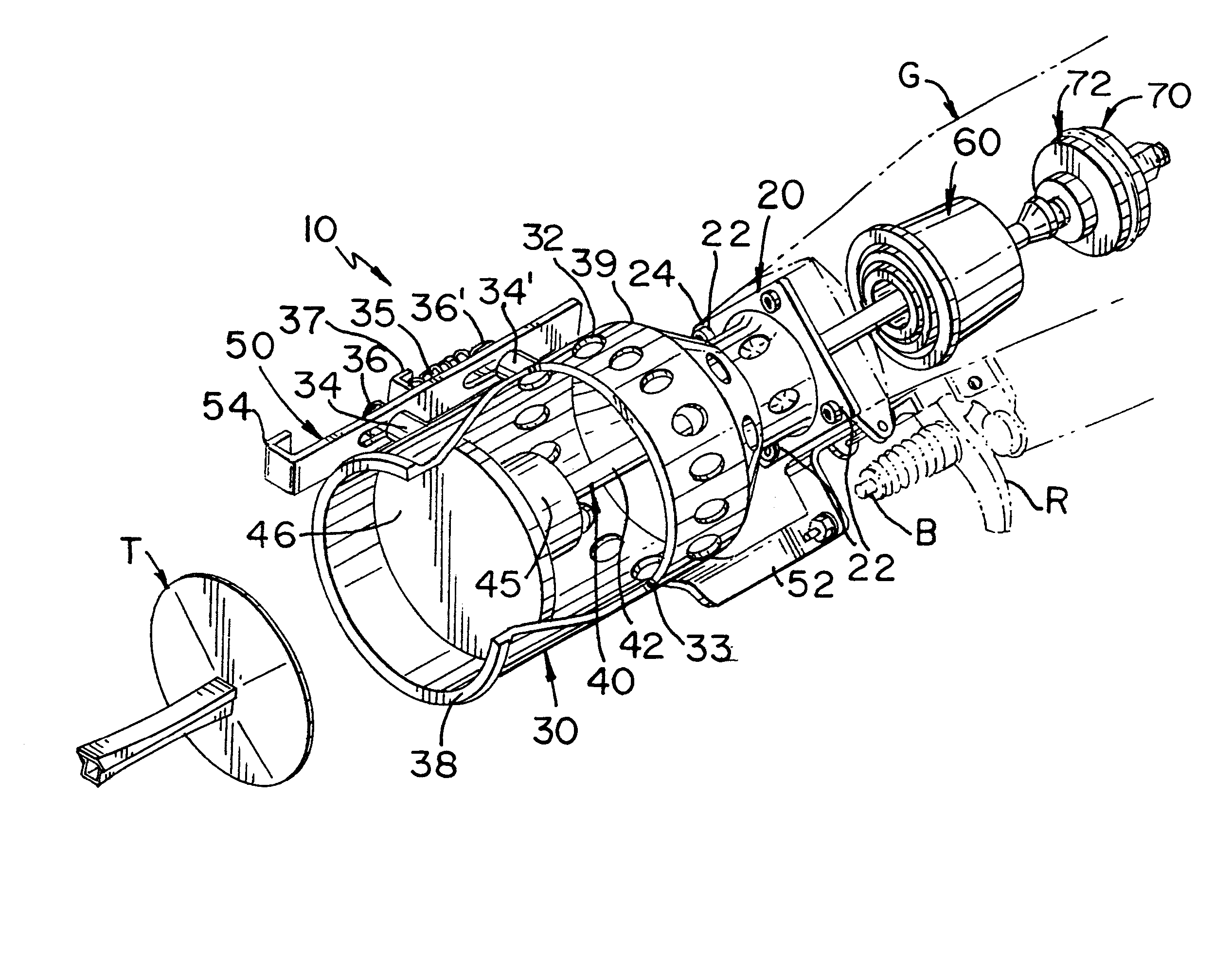
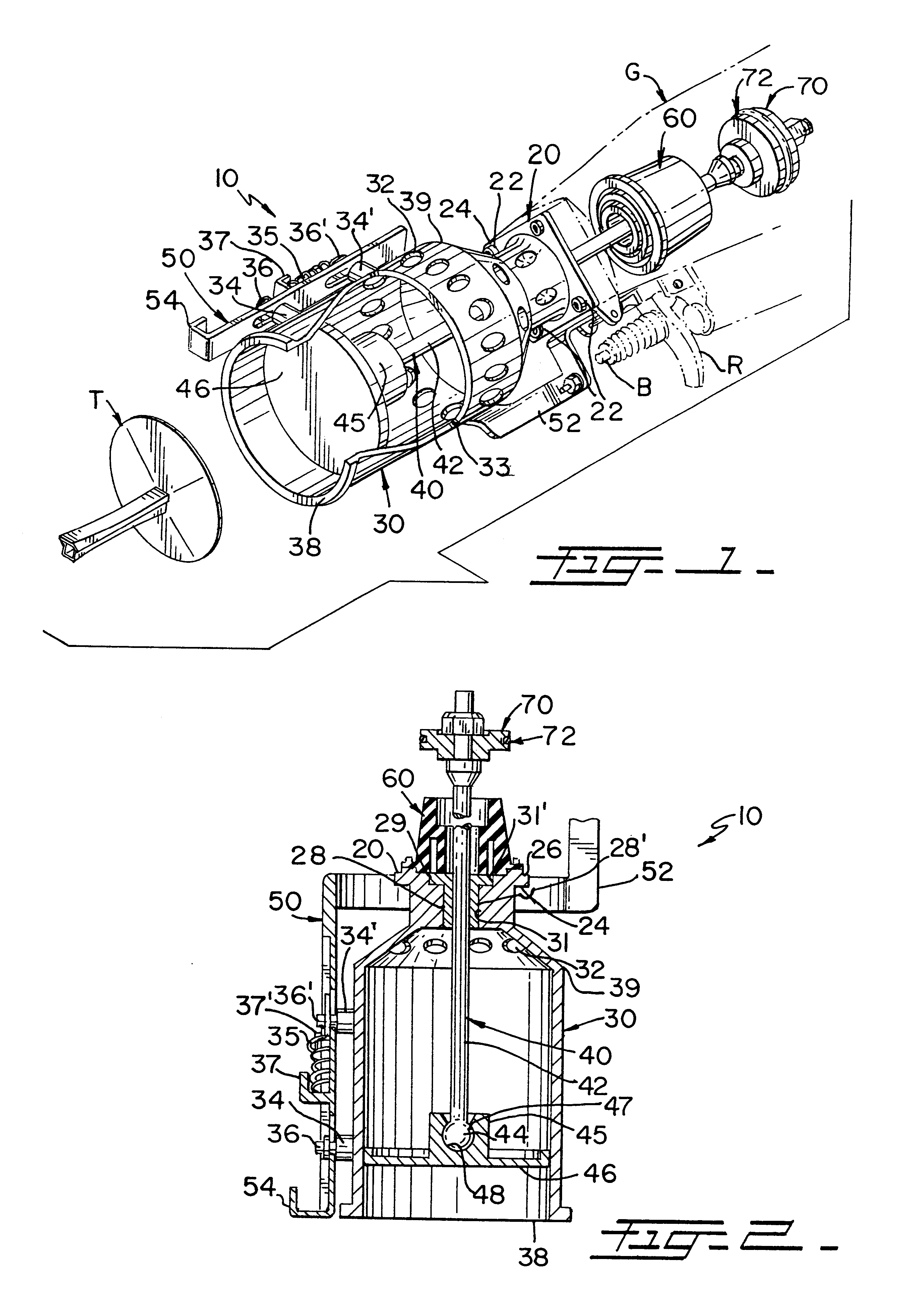
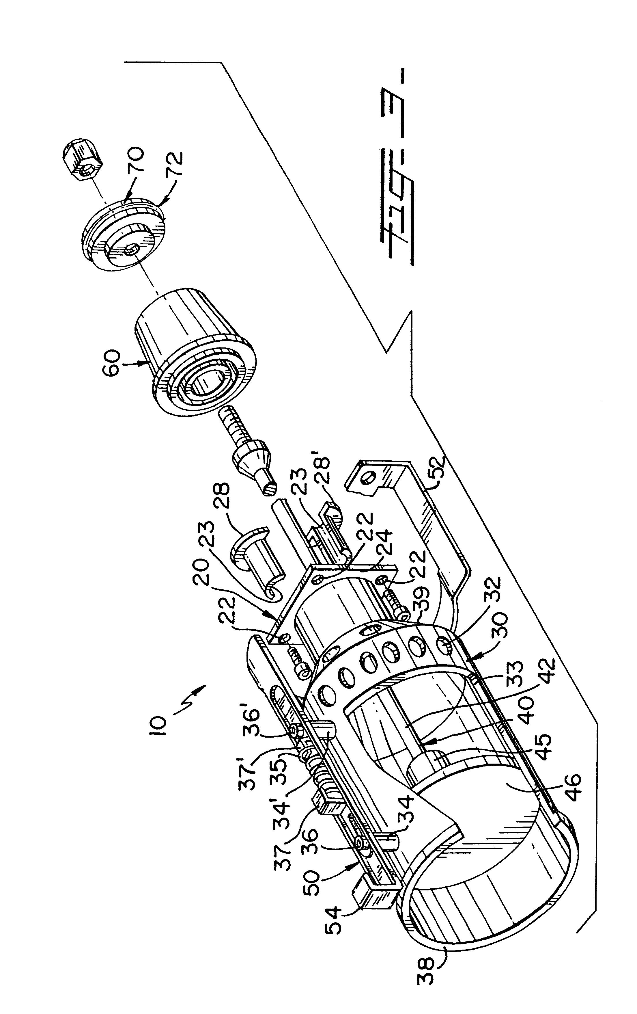
Referring now to the drawings, where the present invention is generally referred to with numeral 10, it can be observed that it basically includes plate 20, receiving assembly 30, hammer assembly 40, and trigger safety mechanism 50.

As seen in FIG. 1, plate 20 has exterior face 24 and interior face 26 (shown in FIG. 2). In the preferred embodiment, plate 20 has a plurality of through holes 22 for attachments of screws, rivets, or similar devices, to removably secure plate 20 to nail gun G (shown in phantom).

Perpendicularly mounted to plate 20 is receiving assembly 30. Receiving assembly 30 is defined by end 38 and end 39 and has a partial cylindrical shape with a longitudinal curved cutout 33. Receiving assembly 30 is slightly larger in diameter than magnetic head 46 for a slidable fit. The magnetism tends to attract base sheet fasteners T to the proper place. Longitudinal curved cut-out 33 decreases approaching end 38, therefore the surface area closer to end 39 is smaller than that...


PUM

PropertyMeasurementUnit
Angleaaaaaaaaaa
Angleaaaaaaaaaa
Forceaaaaaaaaaa

Abstract

A device for base sheet fasteners used in conjunction with nail gun. The nail gun includes main and security triggers that a user has to simultaneously activate while lifting and dropping the nail gun. A slidable spring loaded longitudinal member is pushed back in line with the housing of a receiving assembly causing a leg to activate the safety trigger. This allows a user to place a base sheet fastener onto a magnetic hammer while the hammer is in the retracted position and upon dropping the nail gun, the magnetic hammer automatically strikes the surface thereby nailing the base sheet fastener in a safe and efficient manner. The resulting device permits the continuous installation of base sheet fasteners on a surface. A substantially cylindrical assembly is provided with a longitudinal cutout with cooperative dimensions to receive the base sheet fasteners.

Description

II. BACKGROUND OF THE INVENTION1. Field of the InventionThe present invention relates to a device for nailing base sheet fasteners, and more specifically, to a device to be used with a pneumatic nail gun.2. Description of the Related ArtPresently when a user needs to affix base sheet fasteners to surfaces (flat), a heavy magnetized manual rod is used. The user places a base sheet fastener onto the magnetic tip of the rod, manually lifts the rod and then forcefully strikes the surface with the rod thereby affixing the base sheet fastener onto the surface. Instead of manually placing these base sheet fastener on surfaces, the present invention allows the user to automatically affix them in safe coordination with the operation and mechanism of a nail gun. The nail gun includes a trigger that a user continuously presses while lifting and dropping the nail gun, allowing the user to place a base sheet fastener onto the magnetic hammer while the hammer is in the retracted position and upon...

Claims


Application Information

Patent Timeline
IPC IPC(8): B25C7/00
CPCB25C7/00
Inventor CABRERA, PEDRO
Owner CABRERA PEDRO
Why Eureka
Try Eureka