Marine anchor release device

Inactive Publication Date: 2005-10-04
BURBACK JOHN ALEXANDER
View PDF9 Cites 18 Cited by
  • Summary
  • Abstract
  • Description
  • Claims
  • Application Information

AI Technical Summary

Benefits of technology

[0012]Another objective of this invention is the ease of installation with minimum equipment or tools.
[0013]It is yet another objective of this

Problems solved by technology

It is almost impossible to free the ancho

Method used


Image

  • Marine anchor release device
  • Marine anchor release device
  • Marine anchor release device

Examples


Example

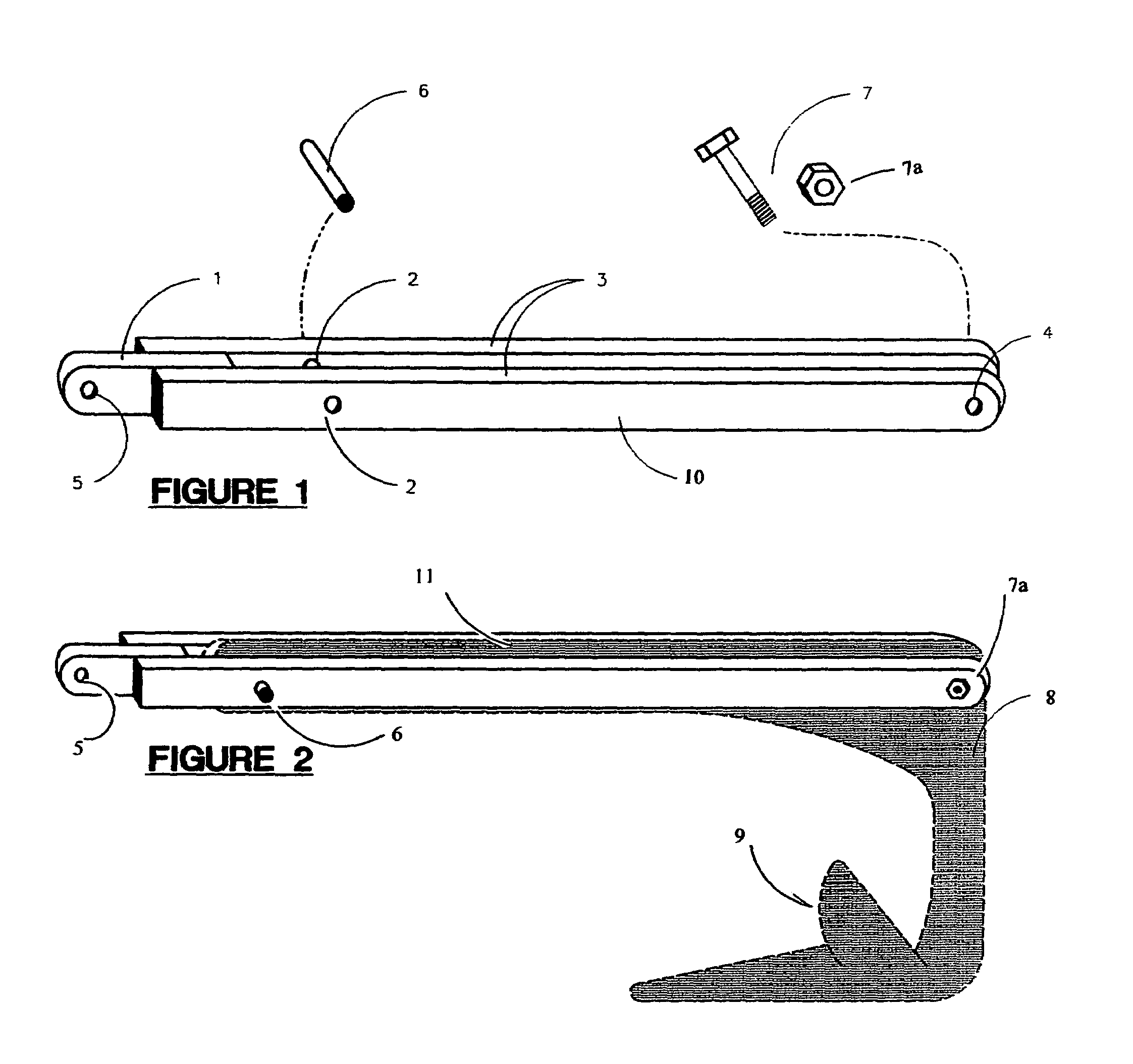
[0018]Referring to FIG. 1, where the present invention is generally referred to with the numeral 10. It can be observed that it basically includes two blade assemblies 3 and a shackle end assembly 1. FIG. 1 also displays a shear pin guiding the same by phantom lines to openings 2 in the blade assemblies 3. There is also shown a bolt 7 with a nut 7a which leads be phantom lines into the openings 4 in the end which is remote from the shackle end assembly 1.

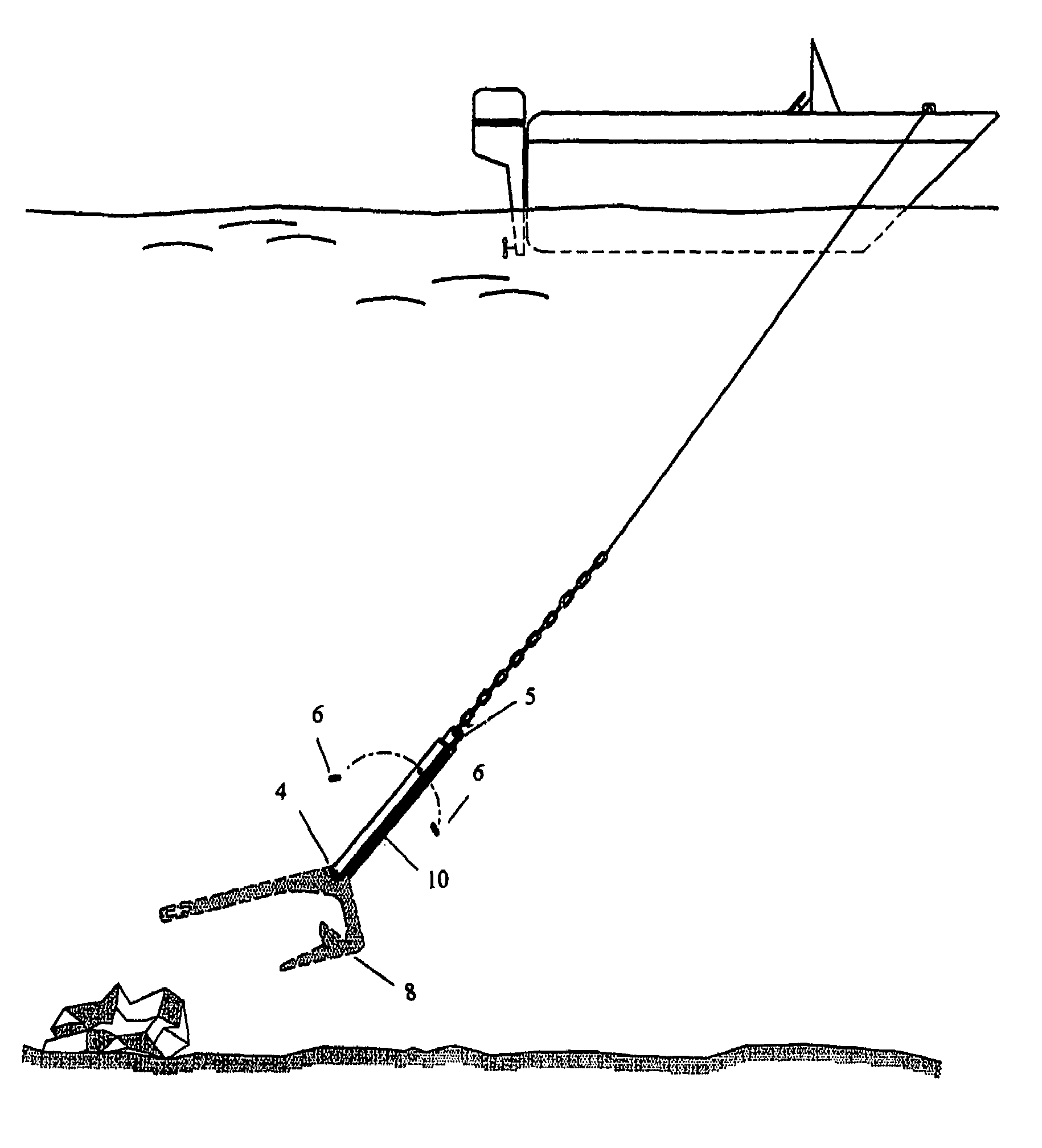
[0019]Referring to FIG. 2, anchor 8 is manufactured by unspecified manufacturers. Invention 10 is designed to be utilized on numerous types and styles.

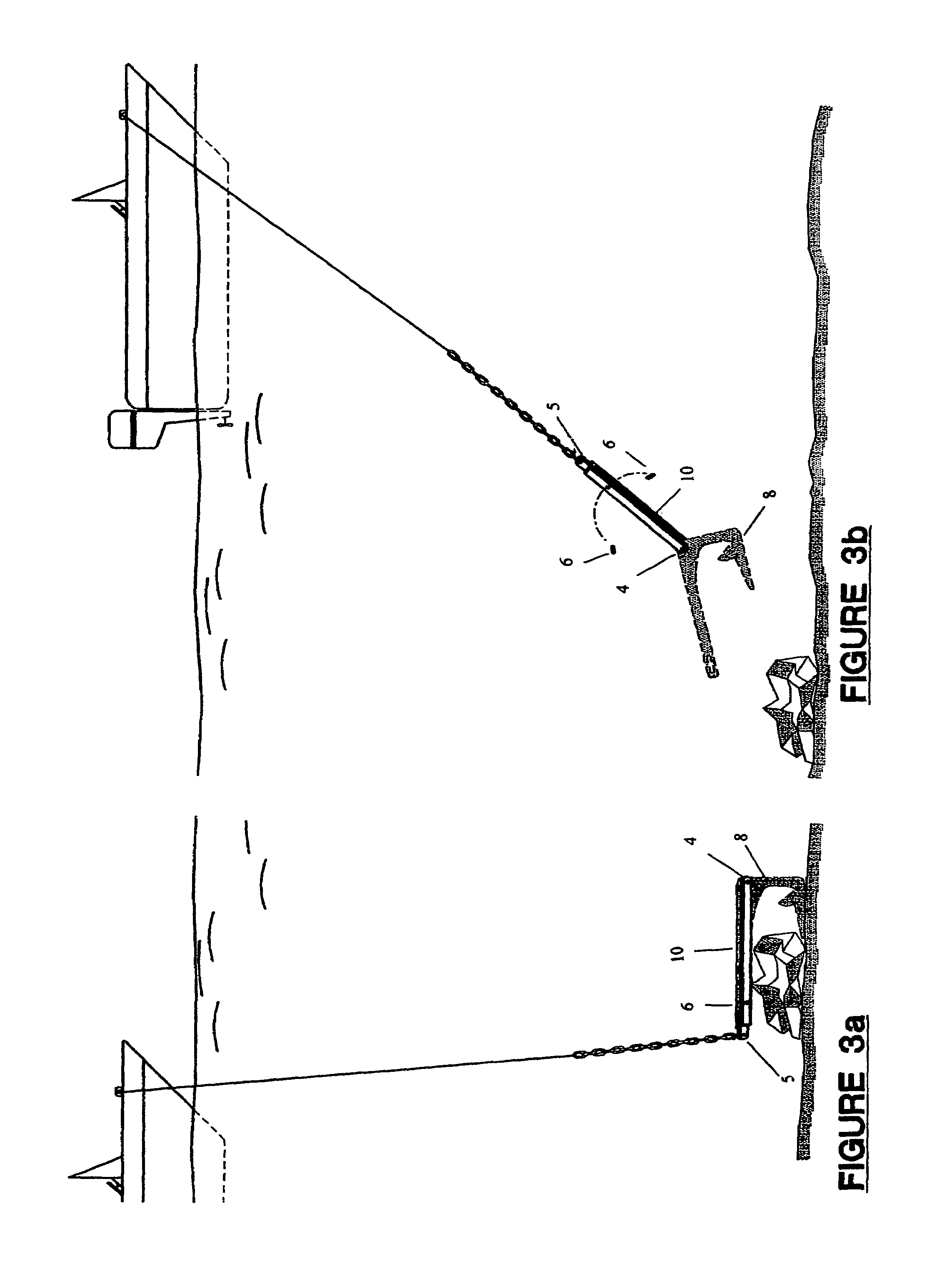
[0020]As seen in FIGS. 1 and 2, the fastening mechanism 7 and 7a is a common nut 7a and bolt 7 in sufficient length and size to fasten 10 to the anchor 8 through hole location 4 and the blades of 10 are held in place against rotation by the shear pin 6 at the hole location 2. The hole opening 5 in shackle end 1 is provided so that a rope or a chain can be secured to device 10. The anc...


PUM


Abstract

A marine anchor release mechanism that can be utilized on several pre-manufactured claw, plow or fluke type anchors for unsnagging the anchors from underwater obstructions. The release mechanism consists of two blade type brackets that run parallel to the shank of an anchor and connected to a rear portion of the anchor. A shear pin is installed through the parallel blade type brackets and the shank or an upper extension of the anchor that is sandwiched there between. The release mechanism is designed to release a snagged anchor by applying a sufficient force when powering the boat over the anchor, the shear pin will give way and the anchor assembly will rotate freely from an angle of substantially 180° with respect to the shackle end of the anchor, thus allowing the anchor to pull free from the obstruction.

Description

CROSS REFERENCE TO RELATED APPLICATIONS[0001](none)STATEMENT REGARDING FED SPONSORED R & D[0002](none)FIELD OF THE INVENTION[0003]The invention relates to marine anchors that are manufactured without a release mechanism such as plow, spade or fluke anchors. This release mechanism or device is designed to be easily installed on new or existing anchors.DESCRIPTION OF THE PRIOR ART[0004]An anchor secures a boat to the bottom of a sea bed by weight of the anchor and by its design. However, typically when an anchor is set, it can become snagged with obstacles such as rocks, reef beds, vegetation or other structures. Often boaters are unable to free their anchors from the obstacles or obstructions and are forced to cut their anchor line, losing a section of the rope or chain and, of course, the anchor itself.[0005]Various devices have been developed to change the attitude of the fluke or the plow of the anchor to a different position so that the plow can easily slip away or from under the...

Claims


Application Information

Patent Timeline
IPC IPC(8): B63B21/24B63B21/32
CPCB63B21/243B63B21/32B63B2021/246
Inventor BURBACK, JOHN ALEXANDER
Owner BURBACK JOHN ALEXANDER
Why Eureka
Try Eureka