Electrolytic regenerator

Inactive Publication Date: 2005-06-28
SLAVCHEV SLAVCHO
View PDF15 Cites 10 Cited by
  • Summary
  • Abstract
  • Description
  • Claims
  • Application Information

AI Technical Summary

Benefits of technology

[0026]It is therefore one of the main objects of the present invention to provide an apparatus that may produce large quantities of hydrogen and oxygen gas from seawater.
[0027]It is another object of the present invention to provide an

Problems solved by technology

None of them, however, include underwater electrolysis tank assemblies comprising turbines that are driven by gas, based on buoyancy principles.
There are

Method used


Image

  • Electrolytic regenerator
  • Electrolytic regenerator
  • Electrolytic regenerator

Examples


Example

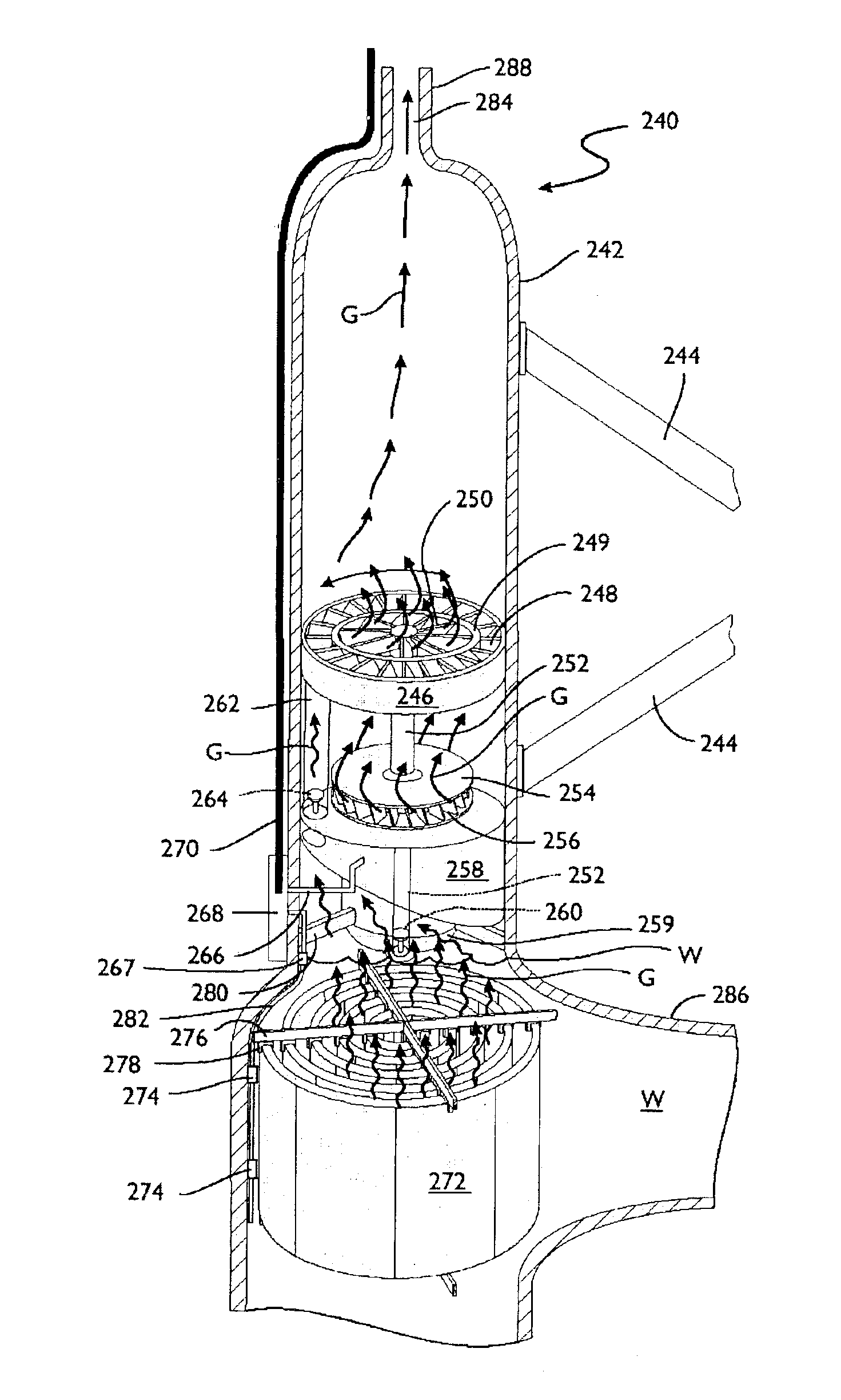
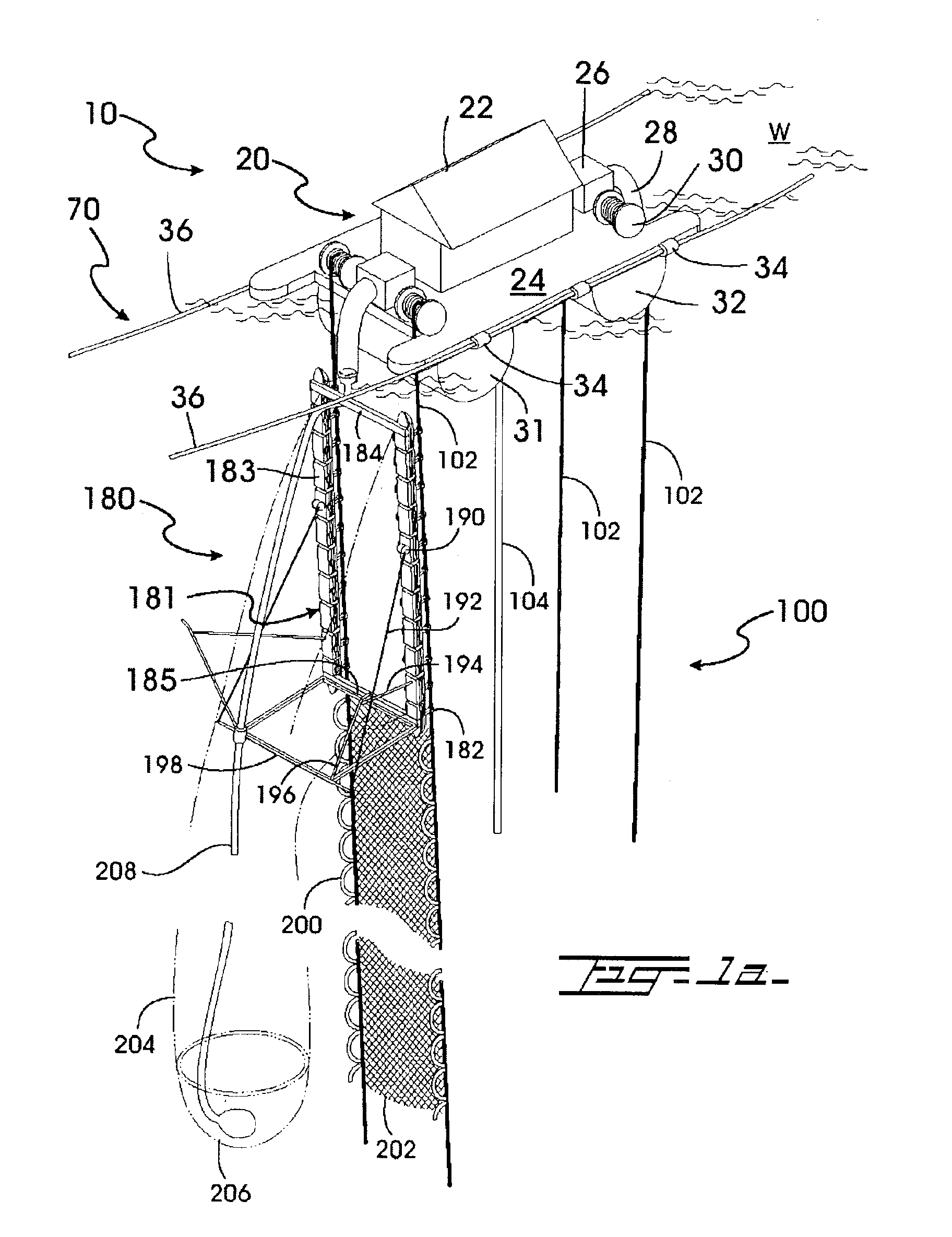
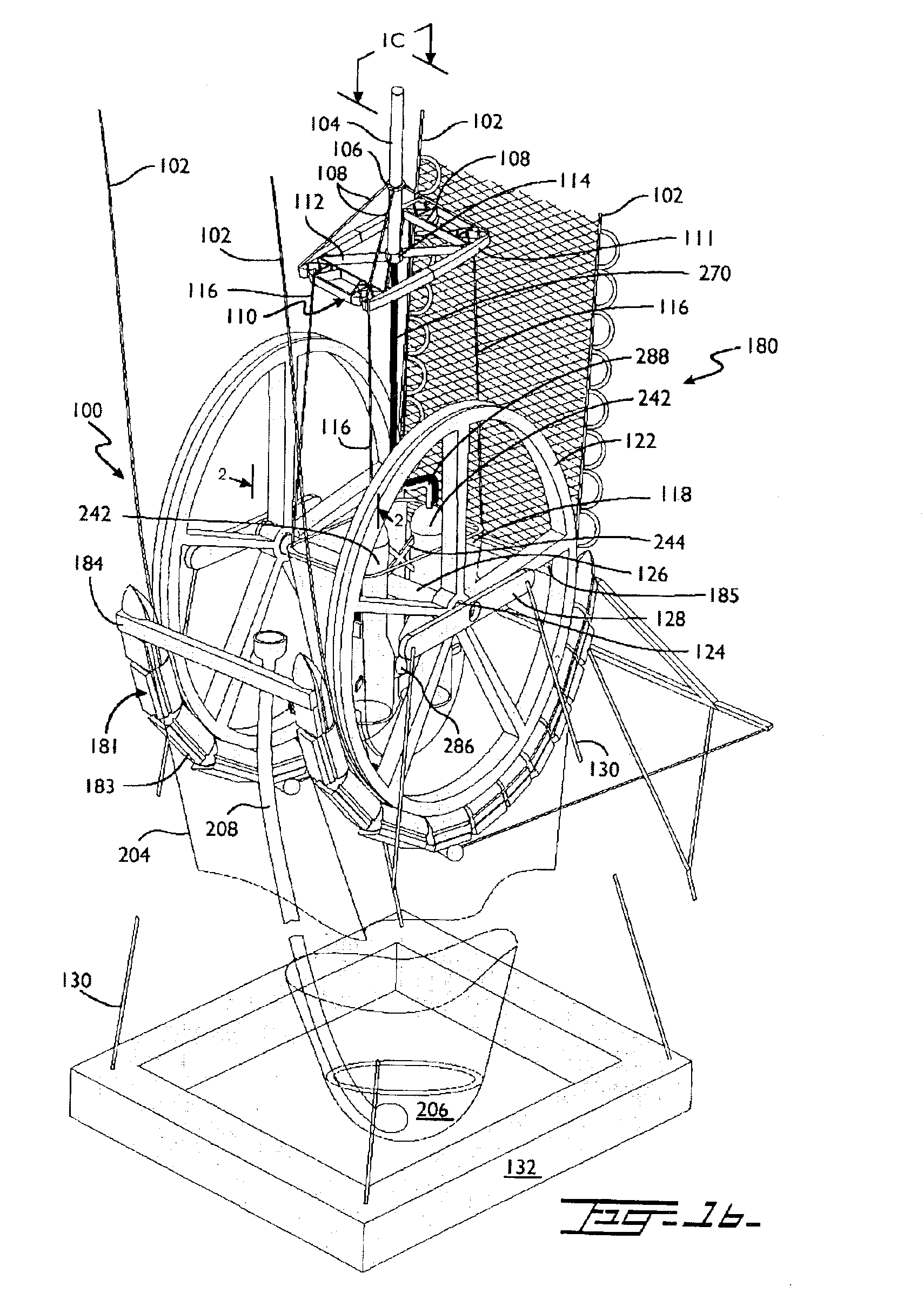
[0040]Referring now to the drawings, where the present invention is generally referred to with numeral 10, it can be observed that it basically includes platform assembly 20, stabilizing assembly 70, pulley assembly 100, collector assembly 180, and electrolysis tank assembly 240.

[0041]Seen in FIG. 1a is the upper portion of instant invention 10. Instant invention 10 operates in a body of water W. Floating on water W is platform assembly 20. Platform assembly 20 comprises a structure 22, as illustrated, resting upon platform 24. Secured onto platform 24 are vacuum assemblies 26. Attached and extending from each vacuum assembly 26, are hoses 28. On each side of vacuum assembly 26 are winch assemblies 30, which spool cables 102. Secured beneath platform 24, tanks 31 and 32 store oxygen and hydrogen gas respectively. Connected to the edge of platform 24, the opposite edge not seen, are guides 34. Guides 34 allow for cable 36 to pass therethrough and stabilize platform assembly 20.

[0042]...


PUM

PropertyMeasurementUnit
Dimensionless propertyaaaaaaaaaa

Abstract

An electrolysis system to be used in a salt-water application at a predetermined depth. The electrolysis system comprises two cylindrical tanks that are connected by an ionic bridge. Enclosed within each tank are turbine assemblies attached to a generator by a shaft. An anode coil is secured to one tank near the bottom and a cathode coil is secured to the other tank near its bottom. Electricity is supplied from an external source to power said anode and cathode coils. Once electrolysis starts to occur, oxygen and hydrogen gas emit and travel towards the top of their respective tanks. As the respective gases pass their respective valves, they turn their respective turbines, which enable their respective generators. Once the generators are providing sufficient power for the anode and cathode coils to perform electrolysis, the external power supply is disconnected. Oxygen and hydrogen is then stored.

Description

BACKGROUND OF THE INVENTION[0001]1. Field of the Invention[0002]The present invention relates to electrolysis systems, and more particularly, to an underwater apparatus to produce electrolysis.[0003]2. Description of the Related Art[0004]Many designs for electrolysis systems have been designed in the past. None of them, however, include underwater electrolysis tank assemblies comprising turbines that are driven by gas, based on buoyancy principles.[0005]There are no electrolysis systems to the best of applicant's knowledge that utilizes buoyancy principles to drive turbines while underwater to produce electrolysis.SUMMARY OF THE INVENTION[0006]Electrolysis, is defined as a chemical change, especially decomposition, produced in an electrolyte by an electric current. As detailed in CHEMISTRY, The Central Science, seventh edition, by Theodore L. Brown, H. Eugene LeMay, Jr., and Bruce E. Bursten; voltaic cells are based on spontaneous oxidation-reduction reactions. Conversely, it is pos...

Claims


Application Information

Patent Timeline
IPC IPC(8): C25B15/00C25B1/04C25B1/00C25B9/00
CPCC25B1/04C25B15/00C25B9/00Y02E60/366Y02E60/36
Inventor SLAVCHEV, SLAVCHO
Owner SLAVCHEV SLAVCHO
Why Eureka
Try Eureka