
Dot recording using specific schemes at the end of recording medium

a technology of recording medium and recording scheme, applied in the direction of digitally marking record carriers, visual presentation using printers, instruments, etc., can solve the problems of insufficient utilization of nozzles, inapplicability of sub-scan feed other than "minute feeding" for and inability to apply the lower end recording schem

Inactive Publication Date: 2001-05-01
SEIKO EPSON CORP
View PDF8 Cites 12 Cited by
  • Summary
  • Abstract
  • Description
  • Claims
  • Application Information

AI Technical Summary

Problems solved by technology

In the conventional technique, the sub-scan feed other than the "minute feeding" may thus not be applicable for the lower end recording scheme.
Another problem is that application of the sub-scan feed other than the "minute feeding" for the lower end recording scheme makes the lower end recording scheme too complicated in some cases.
Even when a large number of nozzles are provided, the number of actually-used nozzles N is restricted to the values that are relatively prime to the nozzle pitch k. In other words, the conventional techniques has a problem that the nozzles provided are not sufficiently utilized.
The first problem is that blotting is often observed between adjacent dots.
The second problem is that accumulation of the mechanical sub-scan feed errors causes a significant positional misalignment between two adjacent raster lines.
These two problems deteriorates picture quality.
As shown in FIG. 14, there is a mechanical lower limit position, which does not mechanically allow any further feed, in the vicinity of the lower end of the sheet.
Since overlapping of recordable raster lines and recordable dots is allowed for the lower end dot recording scheme, the conditions C1' through C3' are not necessarily satisfied.

Method used


Image

  • Dot recording using specific schemes at the end of recording medium
  • Dot recording using specific schemes at the end of recording medium
  • Dot recording using specific schemes at the end of recording medium

Examples


first embodiment

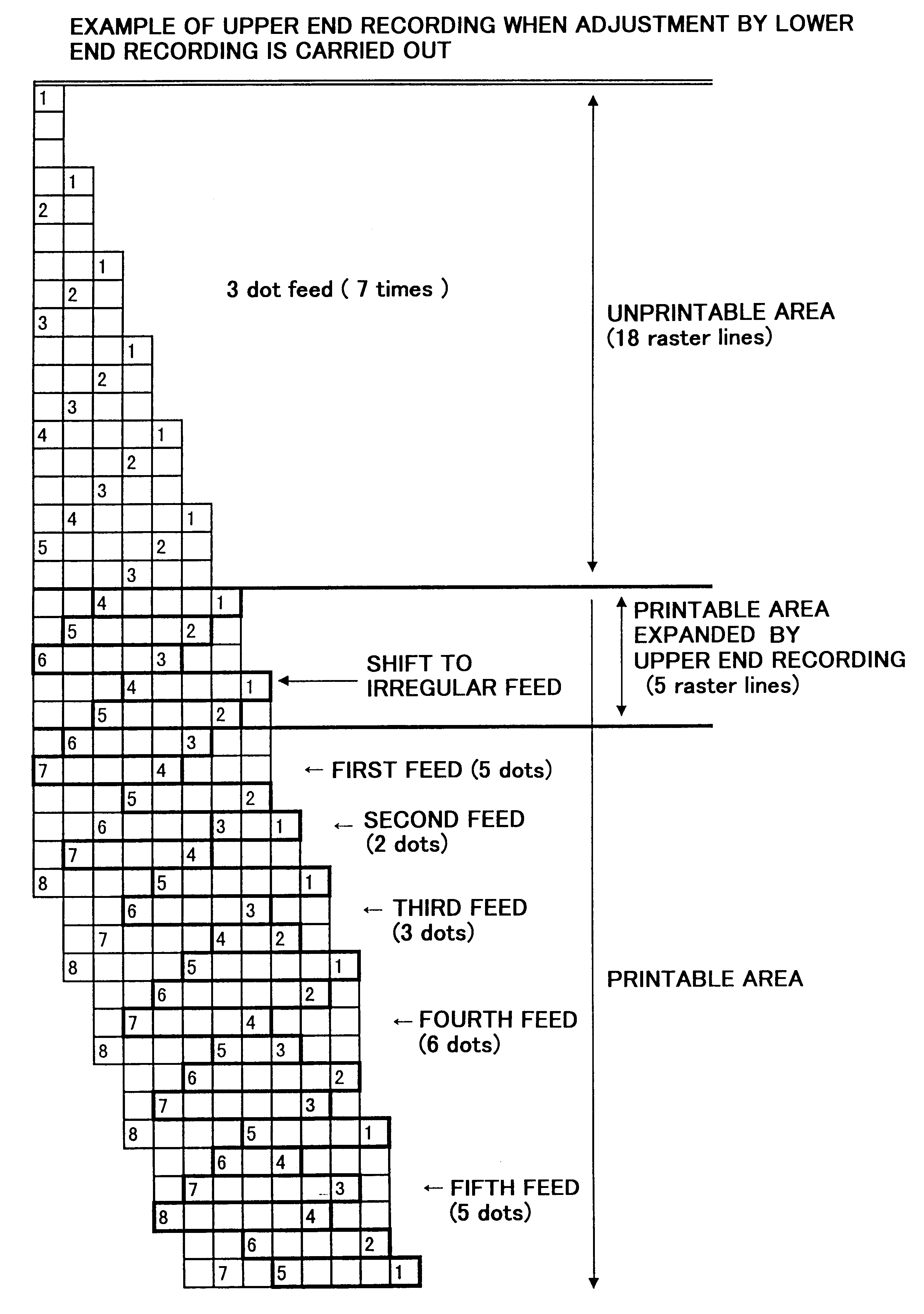
of the lower end recording scheme in the The dot recording scheme of FIGS. 17 and 18 is similar to that of FIGS. 15 and 16. The only difference from that of FIGS. 15 and 16 is that the lower end line of the print execution area is set above the lower end line of the printable area as shown in FIG. 18. This is because the position of the lower end line of the print execution area on the sheet depends upon the sheet settings in the printer driver and the page settings in the applications program. In actual procedure, the lower end line of the print execution area is determined according to the sheet settings and the page settings, and parameters of the lower end dot recording scheme is determined so that the printable area includes the lower end line of the print execution area.

In the example of FIG. 18, it is determined whether or not the 5-dot sub-scan feed is to be changed to the transient feed of one dot in the following manner. When the 5-dot sub-scan feed in the course of the i...

example 2

In Example 2 of the lower end recording scheme, the dot positions to be recorded by the respective nozzles during each main scan are determined based on the history of dot recording in the middle area recording scheme. By way of example, the raster line on the lower end of FIG. 19 is scanned by the first nozzle in the second main scan of the lower end recording scheme. Recording of this raster line, however, has been completed by the seventh nozzle and the third nozzle in the middle area recording. The first nozzle accordingly does not record any dots on this raster line. In the example of FIG. 20, those raster lines which are scanned by three different nozzles are not recorded by the thirdly-passing nozzle. On the raster lines where some dot positions have been left unrecorded in the middle area recording, on the other hand, the lower end recording scheme executes recording of the remaining dot positions.

FIGS. 21 and 22 show Example 3 of the lower end recording scheme in the first ...

example 3

In Example 3 of the lower end recording scheme, the dot positions to be recorded by the respective nozzles during each main scan are determined based on the history of dot recording in the middle area recording, although the details are not described here.

FIGS. 23 and 24 show Example 4 of the lower end recording scheme in the first embodiment. The scanning process of FIGS. 23 and 24 up to the (n+7)-th sub-scan feed is identical with that of FIGS. 13 and 14 without the lower end recording scheme. The example of FIGS. 23 and 24 changes the (n+8)-th sub-scan feed of 6 dots to the transient feed of 3 dots and shifts to the lower end recording scheme where the constant sub-scan feeds are applied.

In Example 4 of the lower end recording scheme, it is determined whether or not the 6-dot sub-scan feed is to be changed to the transient feed of 3 dots in the following manner. When the 6-dot sub-scan feed in the course of the irregular feeding of the middle area recording causes the lower-end n...


PUM


Abstract

Dot recording is carried out according to a first recording mode in the vicinity of an upper end of a record execution area on a recording medium, according to a second recording mode in a middle portion of the record execution area, and according to a third recording mode in the vicinity of a lower end of the record execution area. The third is different from the second recording mode at least in a sub-scan feed amount. In order to use a predetermined sub-scan feed pattern for a selected one of the first recording mode and the third recording mode, sub-scan feed pattern in the other mode is determined.

Description

1. Field of the InventionThe present invention relates to a technique of recording dots on a recording medium with a dot recording head, and more specifically to a dot recording technique using specific recording modes at upper and lower ends of the recording medium to expand a recordable area on the medium.2. Description of the Related ArtSerial scan-type printers and drum scan-type printers are dot recording devices which record dots with a recording head while carrying out scans both in a main scanning direction and a sub-scanning direction. In these types of printers (especially, ink jet printers), a different recording scheme from that executed in a middle portion of the recording medium is performed in the vicinity of an upper end and a lower end of the recording medium in order to expand the area in which the recording can be carried out. (The area will be hereinafter referred to as the "record execution area" or the "print area".) In this specification, the recording scheme ...

Claims


Application Information

Patent Timeline
IPC IPC(8): B41J2/21G06K15/10G06K15/02B41J2/01B41J2/485B41J2/51
CPCB41J2/2132G06K15/107
Inventor SATO, AKITO
Owner SEIKO EPSON CORP
Learn More