
Computer pointing device and method of use

a computer and pointing device technology, applied in computing, instruments, electric digital data processing, etc., can solve the problems of biomechanical stress to the user, discomfort or difficulty in operation, and many of the currently available computer pointing devices have disadvantages, so as to reduce biomechanical stress, facilitate and most comfortable use, and reduce biomechanical stress

Inactive Publication Date: 2001-05-08
SHEARN PATRICK M
View PDF4 Cites 19 Cited by
  • Summary
  • Abstract
  • Description
  • Claims
  • Application Information

AI Technical Summary

Benefits of technology

The present invention is directed to a computer pointing device which has a moldable body wherein a user can mold or form the body into a plurality of shapes. This novel feature permits the user to both (1) form the body into a shape that is easier and most comfortable to use, and (2) during a work period, periodically change the body shape to lessen biomechanical stress. Additionally, the present invention includes selectively positionable control buttons which can also be placed to fit the user, and periodically moved to lessen biomechanical stress. These design features provide an ergonomic computer pointing device which allows the user to change both the body shape and the location of the control buttons over the course of a work period, thus reducing overall biomechanical stress, while still maintaining the accuracy with which the computer pointing device is controlled and actuated.

Problems solved by technology

Many of the currently available computer pointing devices have disadvantages however.
First, the computer pointing device may not fit the hand of the particular user, and therefore may cause discomfort or difficulty of operation.
Additionally, prolonged use of the computer pointing device can cause biomechanical stress to the user.

Method used


Image

  • Computer pointing device and method of use
  • Computer pointing device and method of use
  • Computer pointing device and method of use

Examples


Embodiment Construction

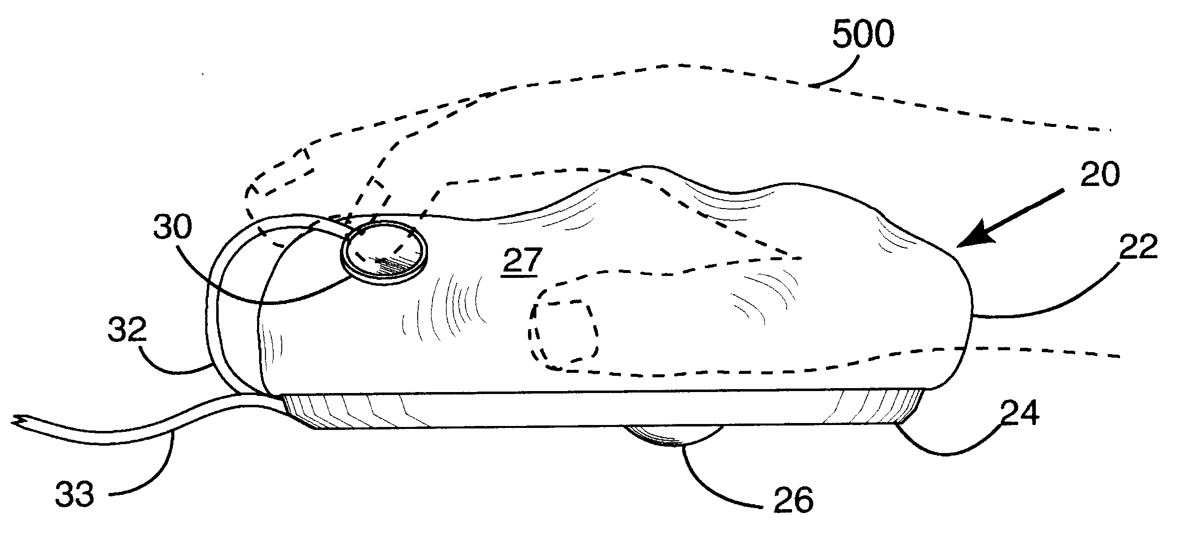
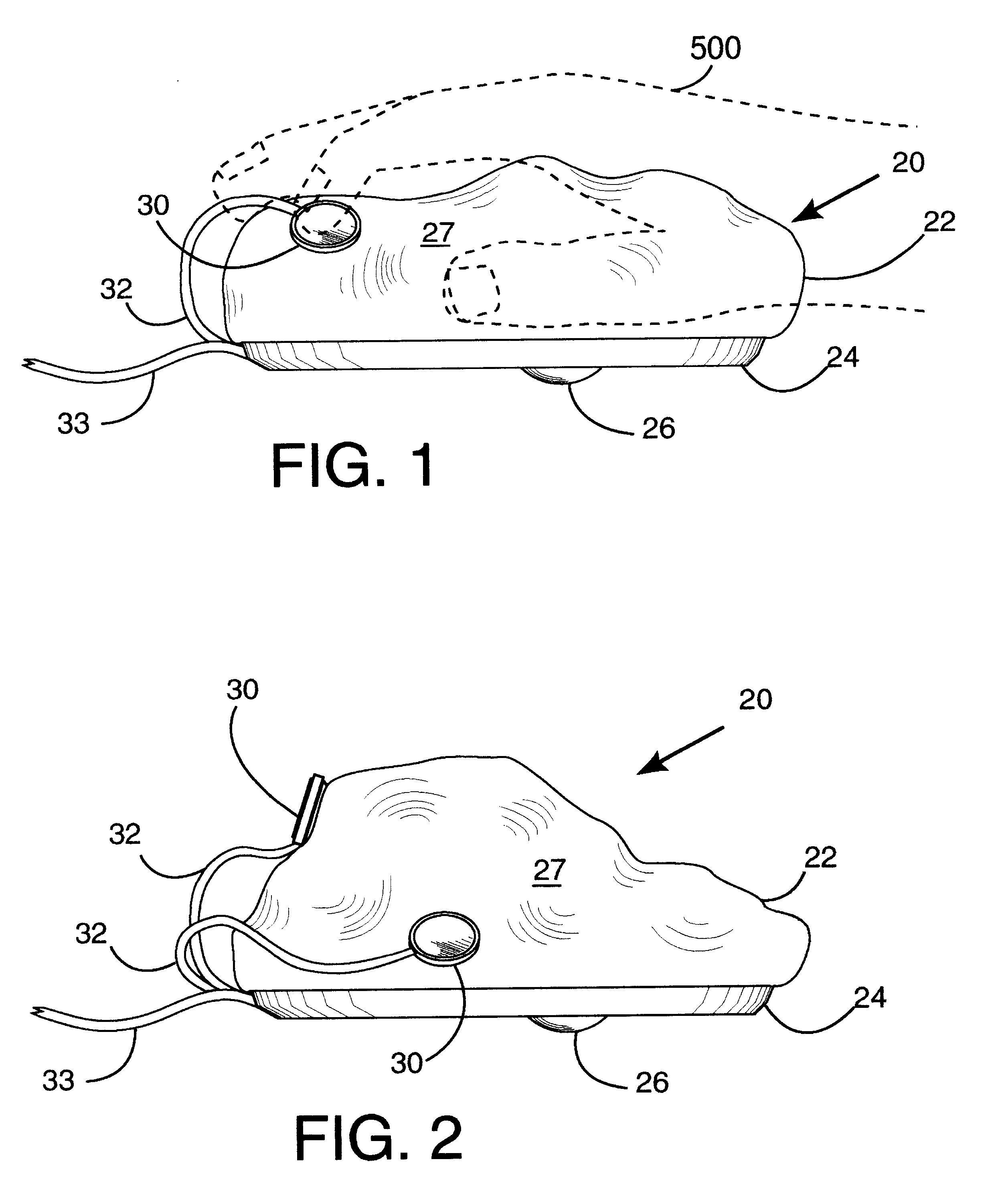
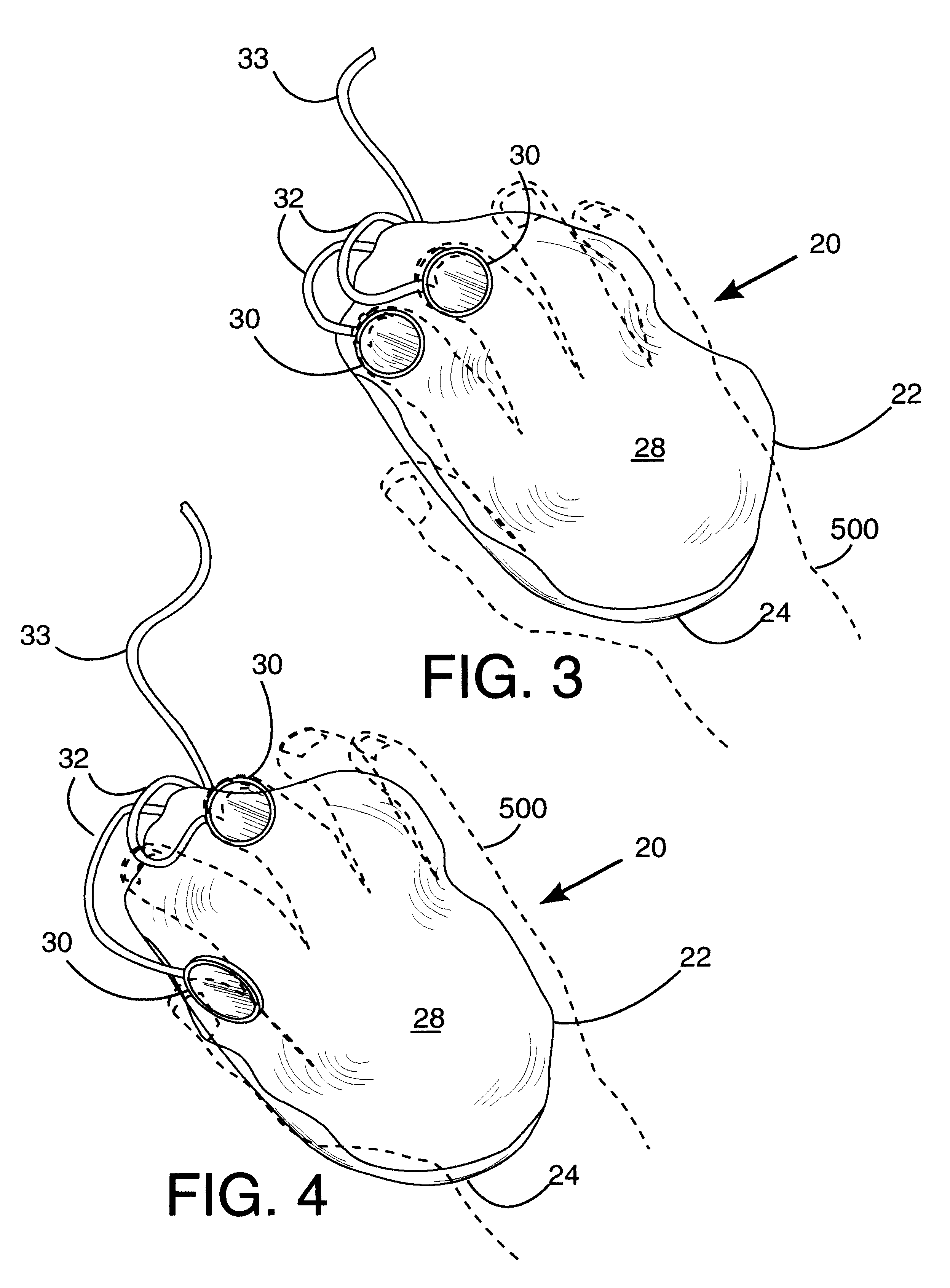
Referring initially to FIGS. 1 and 2, there are illustrated side elevation views of a computer pointing device in accordance with the present invention, generally designated as 20. Computer point device 20 includes a moldable body 22 connected to a base 24. Base 24 includes a motion sensing device and electronic circuitry (not shown), which are well known in the computing art. In the embodiment shown, the motion sensing device includes a rotatable (rollable) ball 26 whose motion is sensed and electronically coupled to a computer screen by means also well known in the computing art. Base 24 could be a modified version of a commercially available unit, to which the moldable body 22 of the present invention is attached. In FIG. 1, moldable body 22 has been molded (formed) by a user into a first shape. The user's hand 500 is shown resting upon the moldable body 22 in a ready-for-use position. In FIG. 2, moldable body 22 has been molded into a second shape. It may be appreciated that mol...


PUM

PropertyMeasurementUnit
Shapeaaaaaaaaaa

Abstract

A hand operated computer pointing device (120) such as a "mouse" includes at least one control button (130) which is selectively positionable to a plurality of desired locations on the surface (127) of the body (122) of the computer point device (120). A user may selectively position the control button(s) (130) to any desired location upon the surface (127) of the body (122) in order to (a) best fit the hand (500) and fingers of the user, and (b) to reduce biomechanical stress. The body of the computer pointing device (120) may be of conventional firm construction (122), or alternatively may be moldable (22) by the user into a plurality of desired shapes.

Description

The present invention pertains to hand operated computer pointing devices, such as a "mouse", and in particular to a computer pointing device which has movable control buttons which, can be positioned by a user to a plurality of desired locations upon the surface of the computer pointing device.Computer pointing devices for positioning a cursor and entering commands into a computer are well known in the art. These devices typically include a body or top portion upon which the user's hand rests, two or three depressible control buttons integral with the body, and a bottom portion or base which contains a motion sensing device and electronics. Some computer pointing devices include a rotatable ball, wherein electronic encoders sense rotation of the ball and generate a signal indicative of the ball's rotation to control movement of a cursor on a computer screen. The rotatable ball extends from the bottom surface of the computer pointing device, and contacts a work surface such as a tab...

Claims


Application Information

Patent Timeline
IPC IPC(8): B29C43/02B29C67/00G06F3/033G06F3/039
CPCB29C43/02B29C67/00G06F3/03543G06F3/039G06F2203/0333
Inventor SHEARN, PATRICK M.
Owner SHEARN PATRICK M
Learn More