System and method for remotely controlling and monitoring a plurality of computer systems

a computer system and remote control technology, applied in the direction of electric controllers, electric apparatus casings/cabinets/drawers, instruments, etc., can solve the problems of wasting valuable computer room space, impracticality of computers, and high cost of computer room space, so as to prevent data loss and minimum space

Inactive Publication Date: 2003-08-19
EPICENTER INC
View PDF16 Cites 190 Cited by
  • Summary
  • Abstract
  • Description
  • Claims
  • Application Information

AI Technical Summary

Benefits of technology

Accordingly, the reader will see that the control and monitoring system of this invention allows a user to apply input to and view the video display output of multiple computer systems. Loss of data is prevented by utilizing multiple processors to handle keyboard and mouse signals and to pass video signals through a video switch. The control and monitoring system may be restarted by a remote operator or have its programming downloaded or uploaded to a

Problems solved by technology

Because computer room space is quite expensive, such computers must be mounted in a rack.
Having a separate video display, character input device, and pointing device for each computer is impractical and wastes valuable computer room space.
(a) consuming valuable rack space
(b) requiring a separate connector for video display, character input, and pointing data and signals on the KVM switch
(c) likelihood of malfunction due to a loose connection or failure of the aforementioned connectors and cables
(d) requiring the user to slide a video display monitor separately from a keyboard and pointing device from the rack before using the video display monitor and the keyboard and pointing device.
However, such a device requires a notebook computer in order to function.
Such devices are relatively expensive and consume more power and space compared to a d

Method used


Image

  • System and method for remotely controlling and monitoring a plurality of computer systems
  • System and method for remotely controlling and monitoring a plurality of computer systems
  • System and method for remotely controlling and monitoring a plurality of computer systems

Examples


Embodiment Construction

--FIGS. 1, 2, 3, and 4

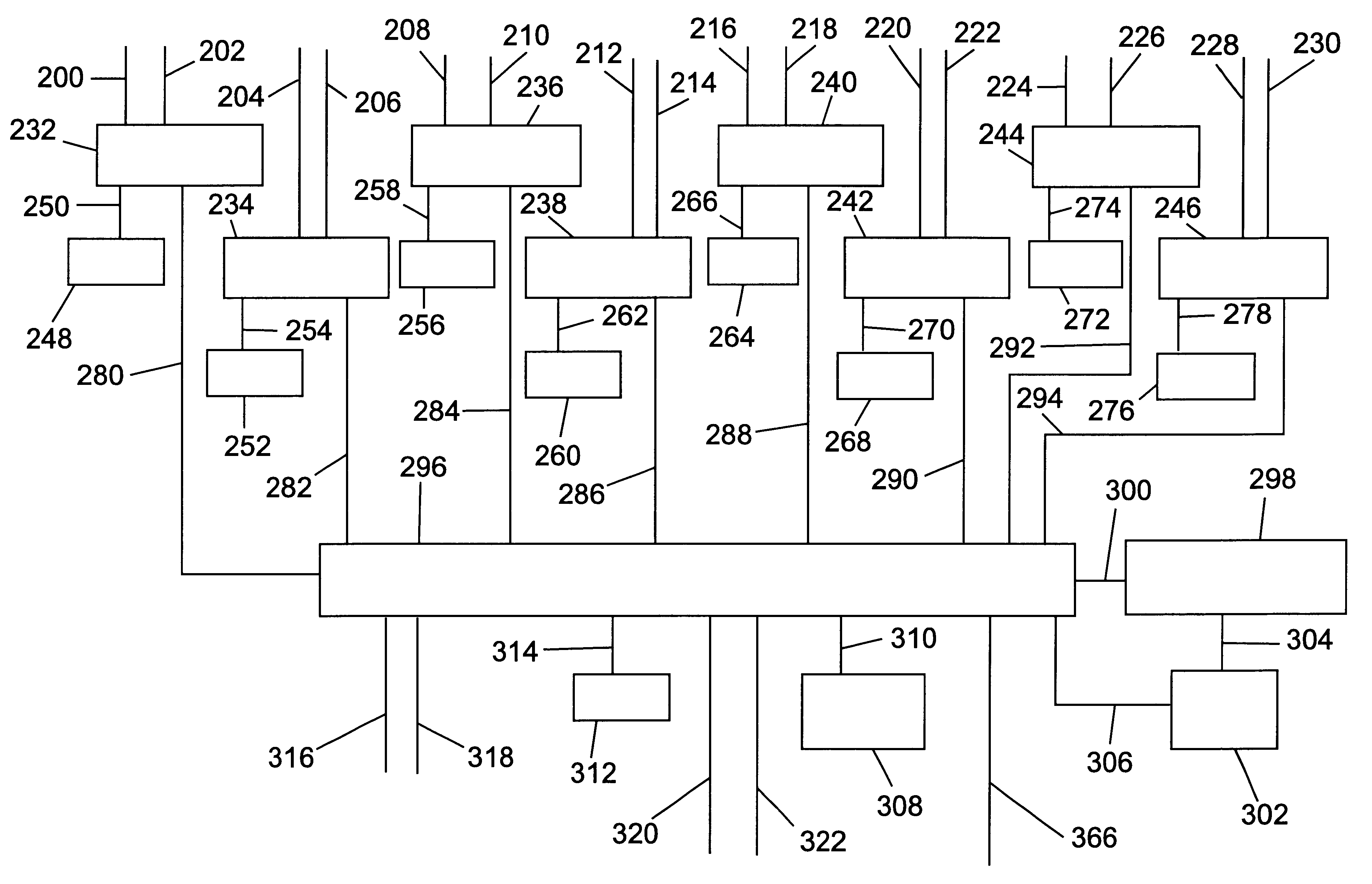
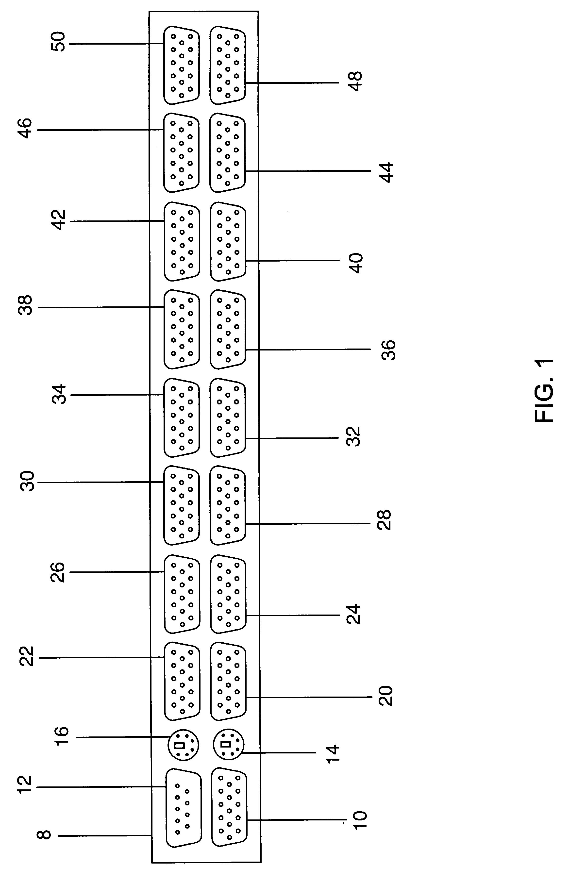
A preferred embodiment of the control and monitoring system of the present invention is illustrated in FIG. 1 (rear view). In the presently preferred embodiment of the control and monitoring system, up to sixteen (16) computer systems may be controlled and monitored from a single control and monitoring system and up to two hundred fifty six (256) if a plurality of control and monitoring systems are connected together. However, those skilled in the art will recognize that the number of possible connections may be modified to accommodate an unlimited number of computer systems.

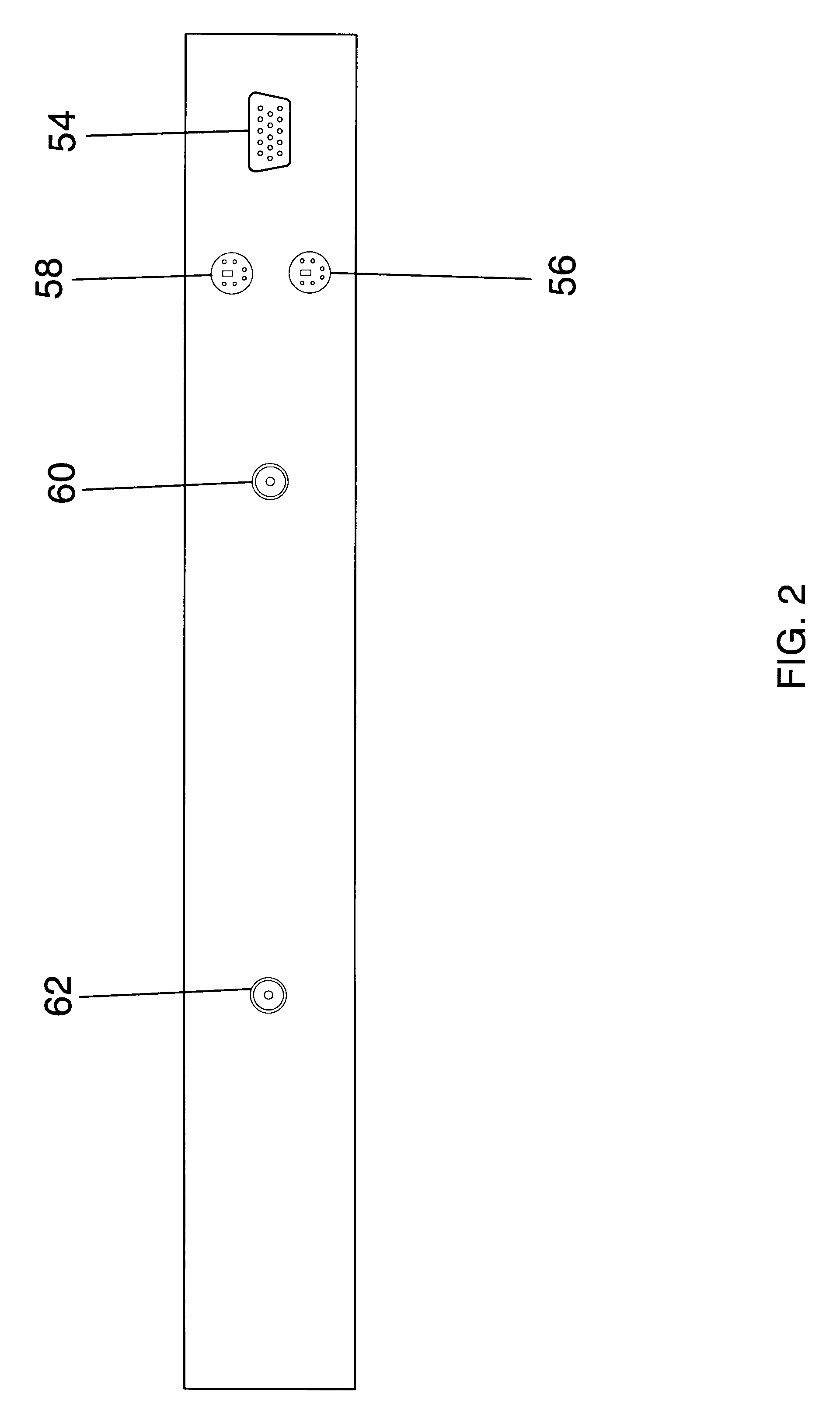
A main unit housing 8 provides a mounting base for the Mini-DIN, DB9, and fifteen position D-sub connectors. An external video display device compatible with the VGA standard may be connected to an External Video Port 10. An External keyboard may be connected to an External Keyboard Port 14. An external mouse or other pointing device may be connected to an External Mouse Port 16. A computer...


PUM


Abstract

An improved control and monitoring system for managing more than one computer system using a witch with a single connector for keyboard, video and mouse signals for each computer being managed. A notebook style display, keyboard, and pointing device attached to the switch provide a human interface. Each computer is attached to the switch using a cable having a single connector at the attachment point to the switch and separate connectors for keyboard, video, and pointing device signals at the attachment point to each computer, thus allowing a greater density of connections to computers without modifying the computers being controlled and monitored. Even greater densities may be realized by designating one switch as a master and attaching additional switches to the master.

Description

Not applicable.REFERENCE TO MICROFICHE APPENDIXNot applicable.COMPUTER PROGRAM LISTING APPENDIX1. Field of the InventionThis invention relates to the control and monitoring of computers, specifically to an improved Keyboard-Video-Mouse switch fully integrated with a video display, character input device, and pointing device.2. Discussion of the Prior ArtMany computers capable of performing general purpose and specialized tasks require a computer room with raised flooring and air conditioning. Because computer room space is quite expensive, such computers must be mounted in a rack. Having a separate video display, character input device, and pointing device for each computer is impractical and wastes valuable computer room space. Keyboard-Video-Mouse (KVM) switches were developed which allows a single video display, character input device, and pointing device to communicate with one or more rack-mounted computers. However, requiring a separate video display, a separate character inpu...

Claims


Application Information

Patent Timeline
IPC IPC(8): G06F3/023
CPCG06F3/023H05K7/1491H05K7/1494
Inventor BEHRENS, EDWARDTU, THOHUA, VANWANG, DAVIDGOODIN, JOHNMATTHES, ROBERT
Owner EPICENTER INC
Why Eureka
Try Eureka