
Method and apparatus to control seismic forces, accelerations, and displacements of structures

a technology of seismic forces and accelerations, applied in the direction of bridges, building repairs, shock proofing, etc., can solve the problems of weak general relationships, adversely affecting the contents of the structure, and the internal acceleration of the stiffer structure is higher

Inactive Publication Date: 2001-05-22
TIPPING STEVEN B +1
View PDF27 Cites 70 Cited by
  • Summary
  • Abstract
  • Description
  • Claims
  • Application Information

AI Technical Summary

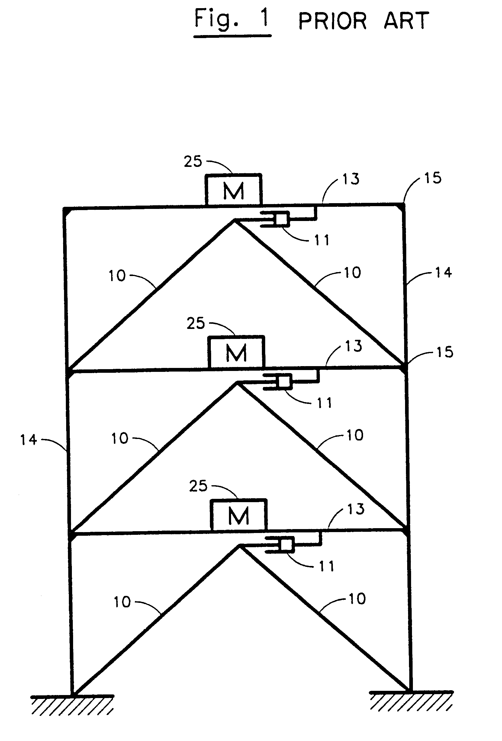
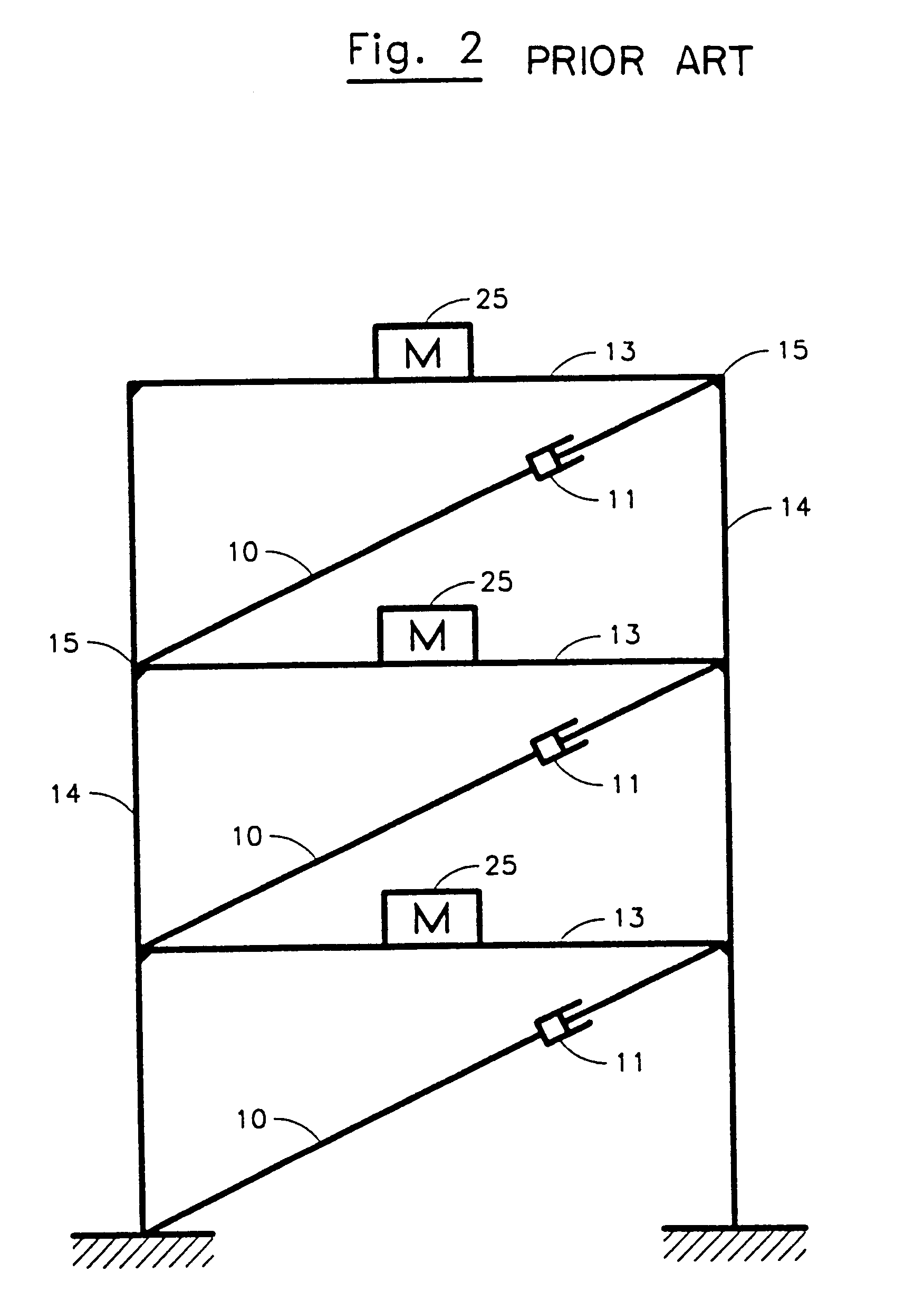
Problems solved by technology

These general relationships may not be valid if the structure is located very close to an earthquake fault that ruptures or if the structure is underlain by extremely soft soils.
The stiffer structure produces higher internal accelerations that can adversely affect its contents.
When a stiff structure is not made strong enough to resist the elastic seismic forces, it sustains structural damage.
By sustaining damage, the structure dissipates the seismic energy.
Internal forces are limited to the elastic strength of the structure.
These larger drifts are in-elastic deformations that can increase non-structural damage.
As with a stiff structure, when the soft structure is not made strong enough to resist the elastic seismic forces, it also dissipates the seismic energy by sustaining structural damage.
The soft structure may undergo large deformations that can adversely affect non structural elements by subjecting them to the structure's deformations.
A decrease in strength usually results in an increase in ductility demand or damping demand;
Relative improvements in strength, ductility and damping of a system usually result in added costs.
Supplemental damping devices may add substantial costs to conventional seismic bracing systems.
To date, the costs associated with the installation of these devices has been a factor in their limited use.
However, there are significant added costs associated with the installation of a base isolation system that are attributed to the isolators, the mote, and the special building system details needed to accommodate the large deformations.
These costs, to date, have limited the use of base isolated systems.

Method used


Image

  • Method and apparatus to control seismic forces, accelerations, and displacements of structures
  • Method and apparatus to control seismic forces, accelerations, and displacements of structures
  • Method and apparatus to control seismic forces, accelerations, and displacements of structures

Examples


Embodiment Construction

The present invention may be utilized with structures such as, for example, buildings, bridges, elevated roadways, and elevated railways. For simplicity and clarity, it will be described with reference to utilizing it with a building.

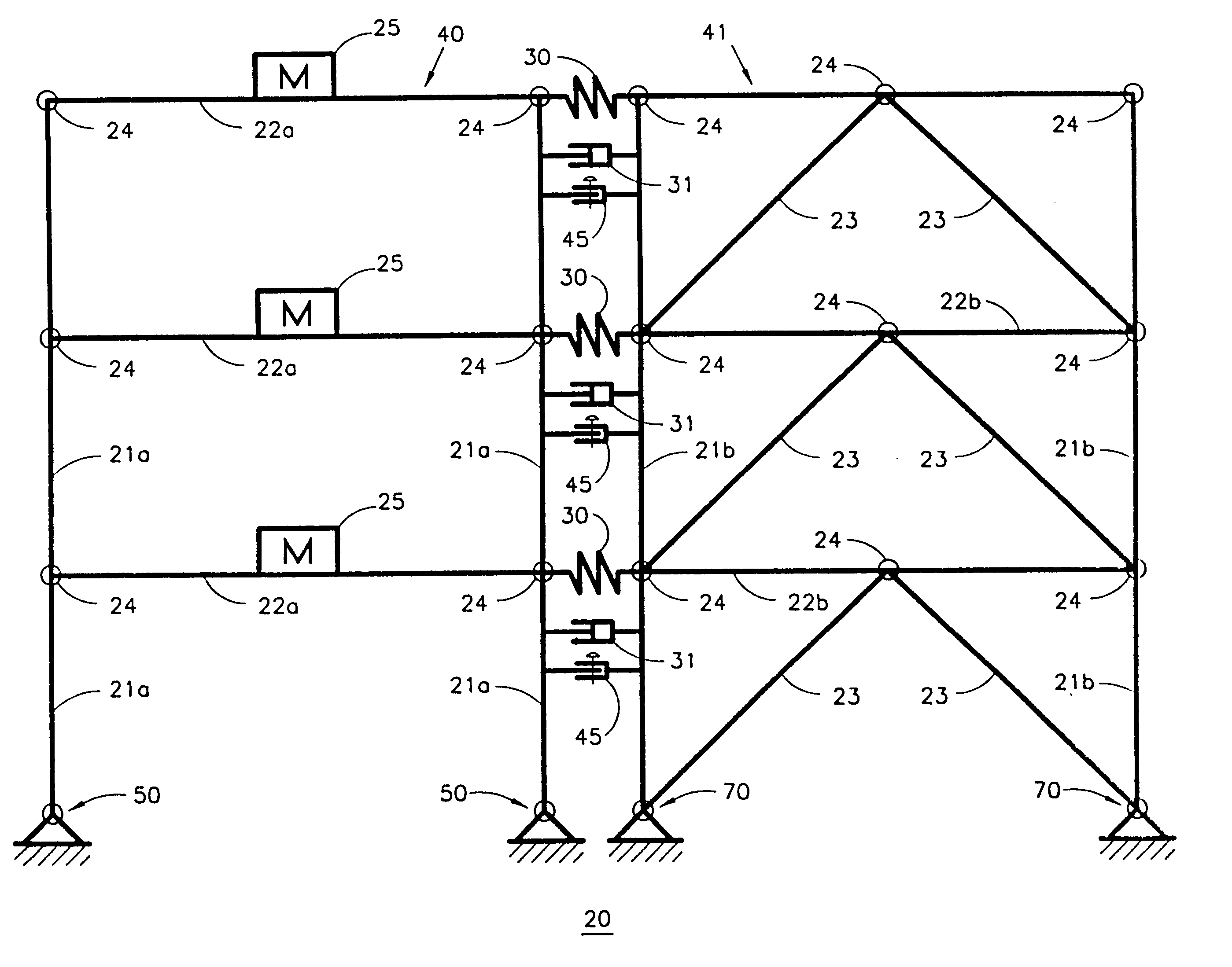
Turning to FIG. 4, a system for damping or limiting internal forces caused by external forces, such as earthquakes, in accordance with the present invention is schematically illustrated. With this arrangement, a tuned, damped structure 20 comprises a gravity frame 40 and at least one reaction frame 41. In this embodiment, gravity frame 40 comprises columns 21a and beams 22a, while reaction frame 41 comprises columns 21b and beams 22b. As can be seen in FIG. 10, the reaction frame also includes braces 23 arranged in a substantially inverted V shape, which could be in a V-shape, X-shape, etc., with one pair of braces present at each floor. The braces, columns, and beams are joined at various locations with joints 24. Additionally, in this embodiment, the ...


PUM


Abstract

A seismic energy dissipation system for use with structures such as buildings, bridges and the like. The system includes a gravity frame, at least one reaction frame, and connection apparatus for connecting the gravity frame and the reaction frame. The connection apparatus includes springs for setting a period of response and energy dissipation units for dissipating energy within the structure, thus controlling the response of a structure with respect to internal forces, accelerations and deformations due to external excitations such as wind or earthquake.

Description

1. Technical FieldThis invention relates to a system for damping and limiting internal forces, accelerations, drifts, etc. caused by external excitations such as earthquakes and wind in structures such as buildings and bridges, and more particularly, to a structural system in which the periods of response, deflection patterns and damping capabilities of the structure are set by the invention in order to dissipate seismic energy and control the internal forces, displacements and accelerations.2. Description of the Prior ArtIn order to protect a structure such as a building or bridge, as well as people who may occupy or be in the vicinity of such structures, seismic force resistive systems have been devised. These systems occasionally include active and / or passive seismic energy dissipation devices. These systems attempt to protect the structure from total collapse and control damage in response to seismic forces created by earthquakes. Typically a local building code sets minimum equ...

Claims


Application Information

Patent Timeline
IPC IPC(8): E04H9/02F16F15/02E02D27/34E01D1/00E01D2/00
CPCE04H9/02F16F15/022E04H9/028E04H9/0235E04H9/0237
Inventor TIPPING, STEVEN B.MAR, DAVID
Owner TIPPING STEVEN B
Learn More