Pressure control valve

Inactive Publication Date: 2001-06-12
ROBERT BOSCH GMBH
View PDF11 Cites 48 Cited by
  • Summary
  • Abstract
  • Description
  • Claims
  • Application Information

AI Technical Summary

Problems solved by technology

Such a limp-home operation places high demands on the durability of both the spring and the valve in the region of the valve seat.
When the pressure control valve is subjected, for example

Method used


Image

  • Pressure control valve
  • Pressure control valve
  • Pressure control valve

Examples


Embodiment Construction

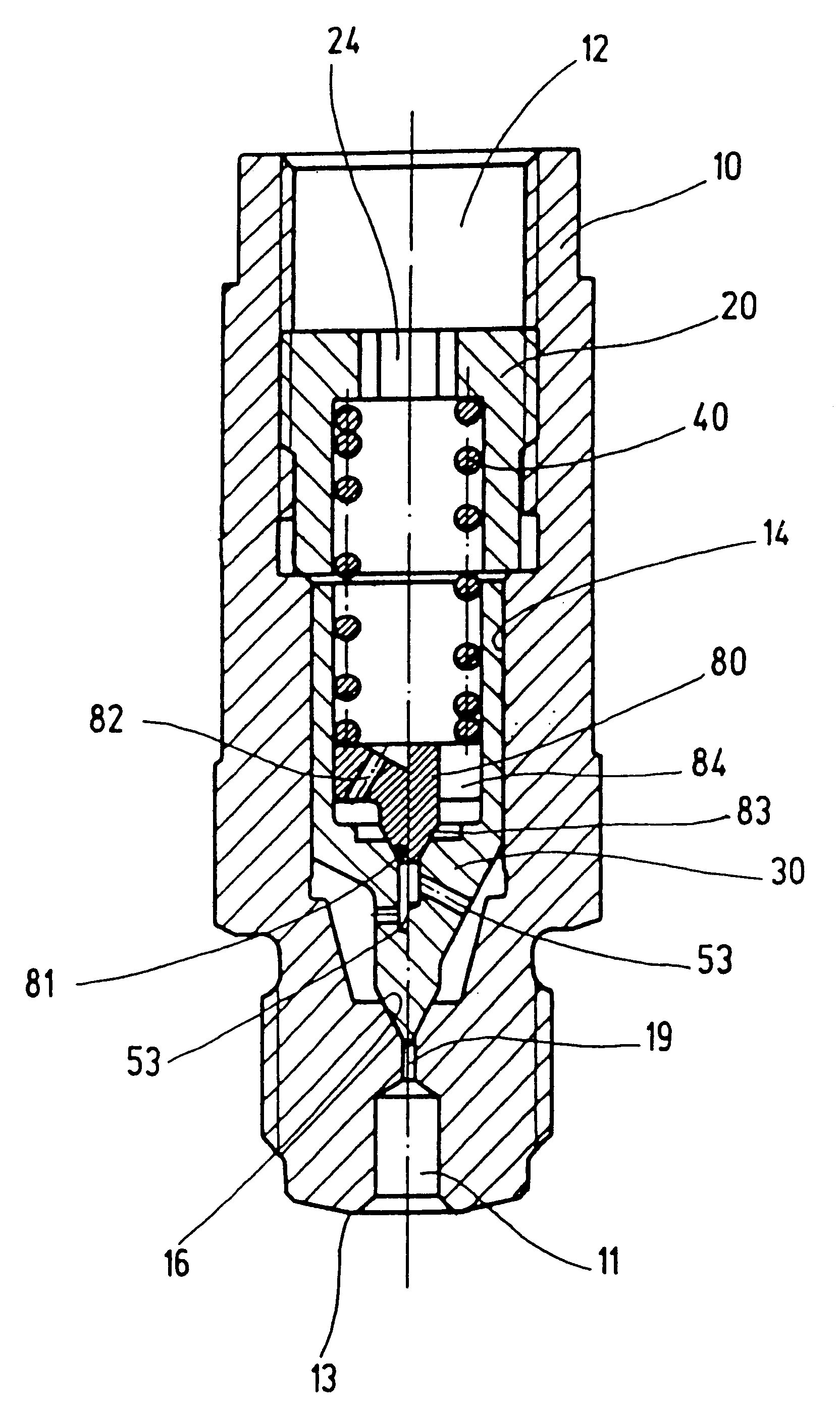
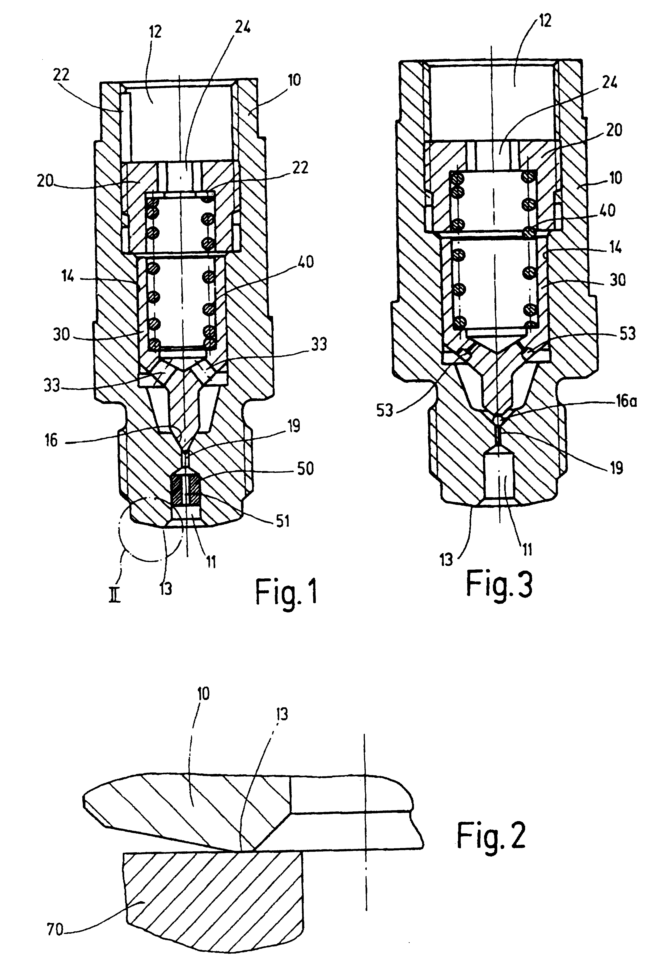
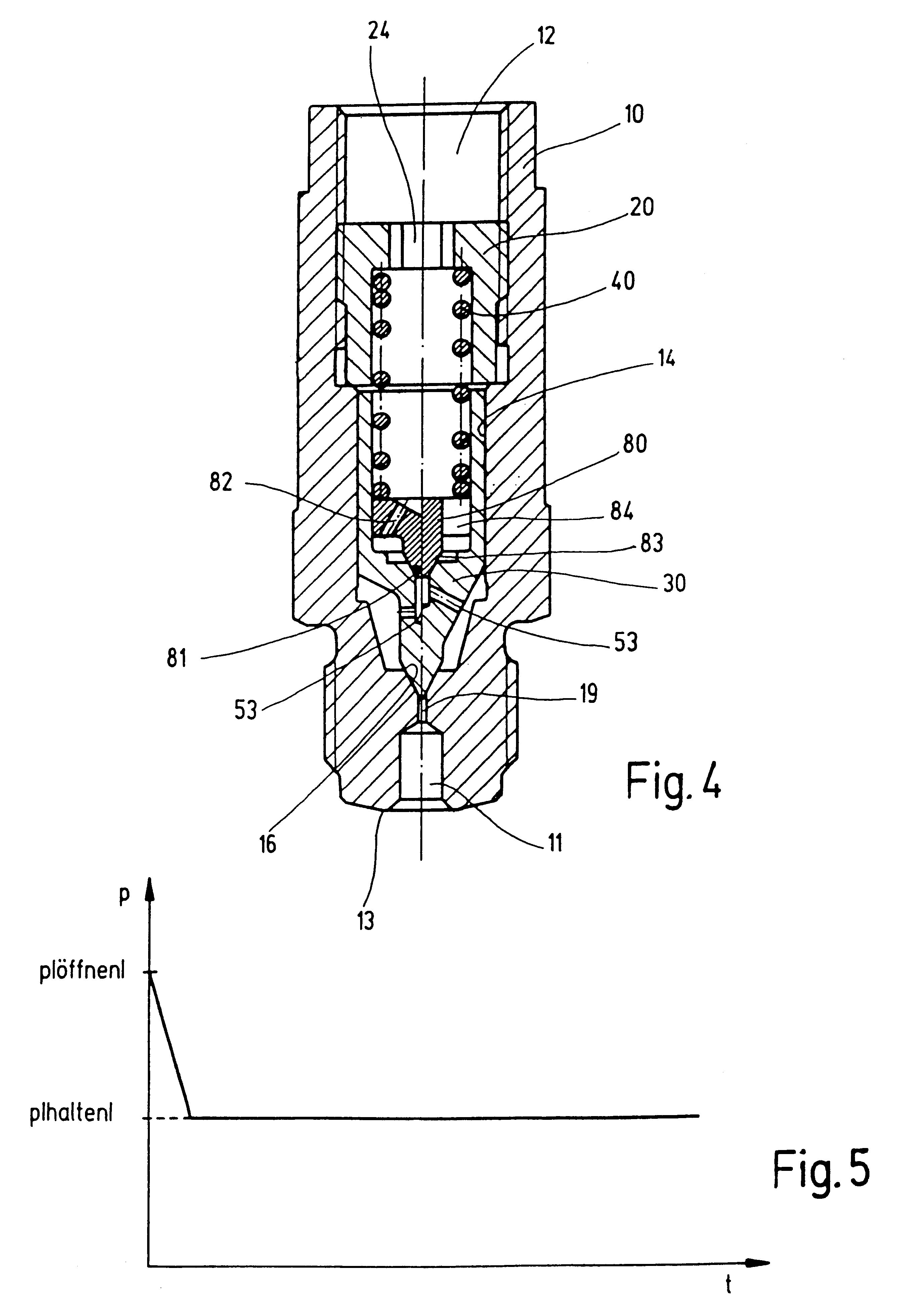
An exemplary embodiment of a pressure control valve shown in FIG. 1 includes a housing 10 with a high-pressure connection 11 and a return connection 12. The housing is provided with a stepped housing bore 14 in the housing, which ends at a valve seat 16 on its end oriented toward the high-pressure connection 11 and in which, on its end oriented toward the return connection 12, a stop 20 is disposed, for example as depicted, by means of being screwed into a thread provided in the housing bore 14. For example, the stop can be secured by means of a Heli-Coil 22, as shown in FIG. 1.

A piston 30 can be moved in the axial direction of the pressure control valve between the stop 14 and the valve seat 16, counter to the spring force of a spring 40. The piston 30 has the shape of a cup-like form, on the interior of which the spring 40 is guided and supported. The stop 20 likewise has the shape of a cup, on the interior of which the spring 40 is guided and supported on its end oriented toward ...


PUM


Abstract

A pressure control valve for a fuel injection apparatus for internal combustion engines, including a housing with a high-pressure connection and a return connection and including a cup-shaped piston, which is disposed in a housing bore, can be moved axially between a valve seat oriented toward the high-pressure connection and a stop oriented toward the return connection, counter to the spring force of a spring acting in the direction of the valve seat, and has at least one through opening that connects the inside of the cup-shaped piston to the housing bore, is characterized in that at least one throttle element is disposed upstream and/or downstream of the valve seat in the flow direction of the fuel.

Description

PRIOR ARTThe invention relates to a pressure control valve for a fuel injection apparatus for internal combustion engines, including a housing with a high-pressure connection and a return connection and including a cup-shaped piston. The piston which is disposed in a housing bore and, can be moved axially between a valve seat oriented toward the high-pressure connection and a stop oriented toward the return connection, counter to the spring force of a spring acting in the direction of the valve seat. The piston and has at least one through opening that connects the inside of the cup-shaped piston to the housing bore.Pressure control valves of this kind have been known for a long time and can be seen, for example, in the German publication "Diesel-Speichereinspritzsystem Common-Rail" [Diesel Common Rail Accumulator Fuel-Injection System] Bosch Technical Instruction No. 1987722054; KH / VDT-0997-DE".The function of a pressure control valve of this kind essentially corresponds to that of...

Claims


Application Information

Patent Timeline
IPC IPC(8): F02M63/00F02M63/02F02M59/46F02M59/00G05D16/10G05D16/04F02M55/00
CPCF02M63/005F02M63/0225G05D16/103G05D16/0402
Inventor HAEBERER, RAINERBUERKLE, FRIEDERCLAUSS, HELMUTRUECKLE, MARKUS
Owner ROBERT BOSCH GMBH
Why Eureka
Try Eureka