Universal transmitter

Inactive Publication Date: 2001-06-19
TSUI PHILIP Y W
View PDF24 Cites 119 Cited by
  • Summary
  • Abstract
  • Description
  • Claims
  • Application Information

AI Technical Summary

Problems solved by technology

The transmission pattern used by one manufacturer is usually incompatible with that provided by other manufacturers.
They are fixed hardware devices and allow very limited flexibility in the encoding/decoding operation or in the modification of the encoding/decoding

Method used


Image

  • Universal transmitter
  • Universal transmitter
  • Universal transmitter

Examples


Example

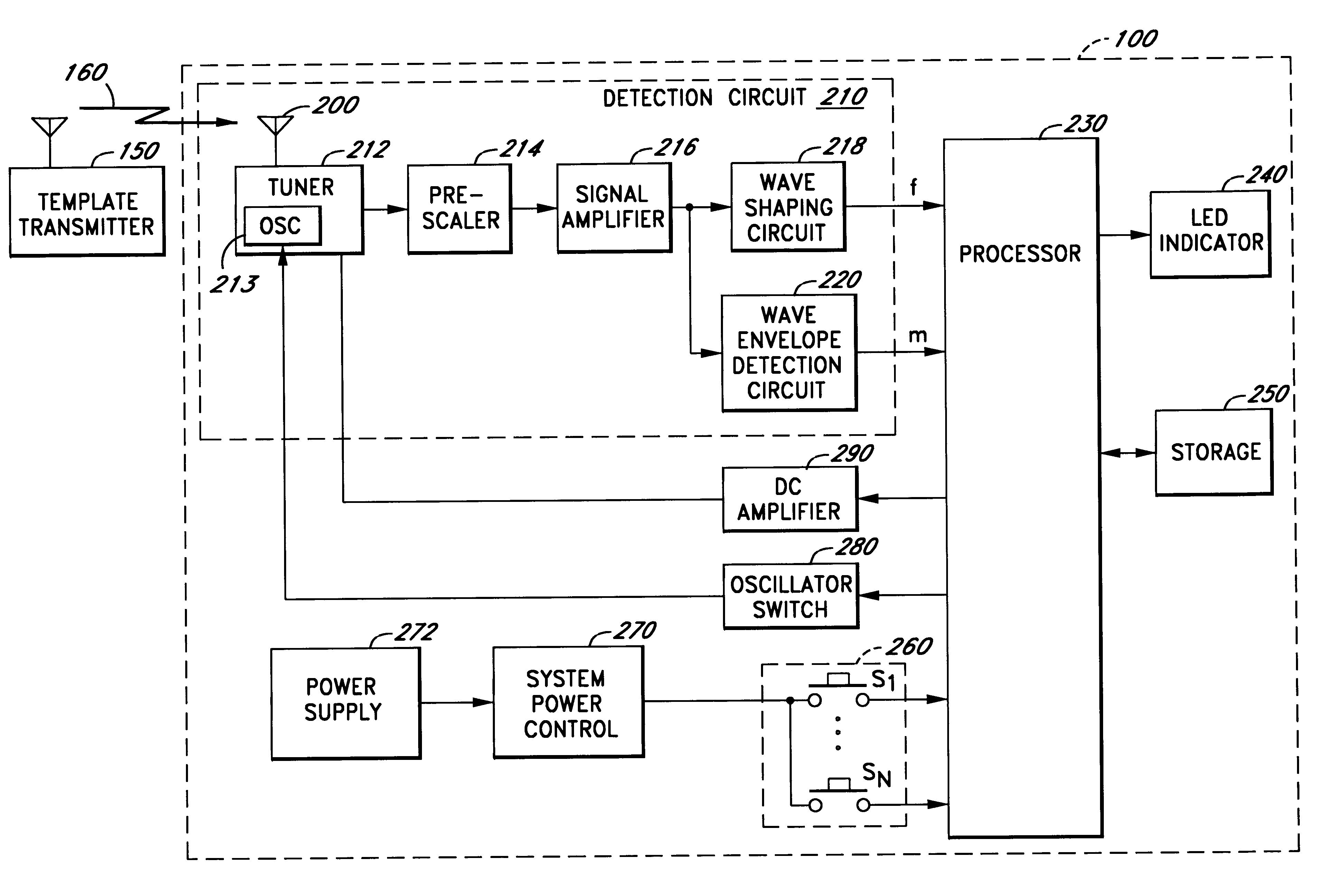
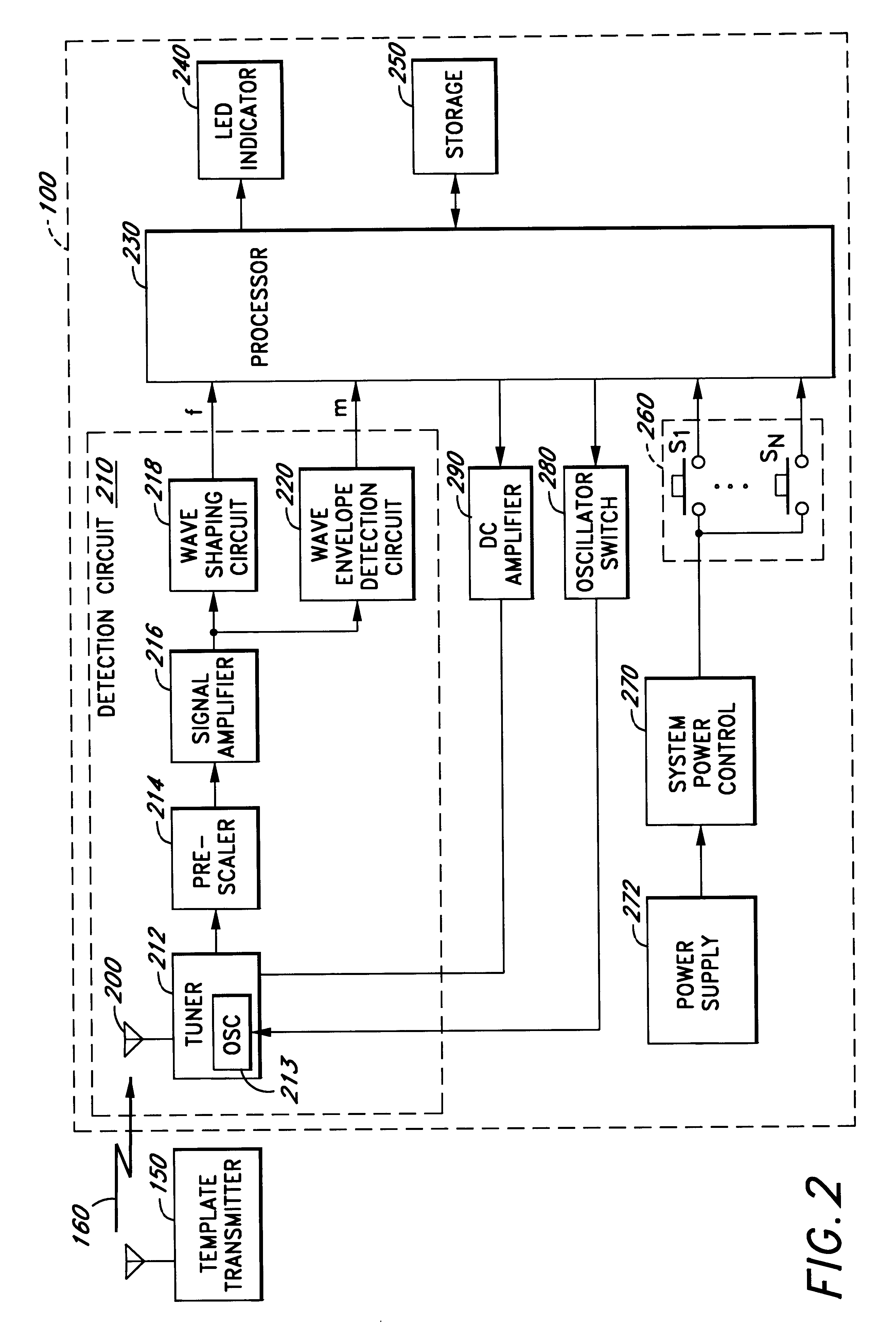
The present invention provides a universal remote control transmitter that may be programmed to actuate any remote control receiver without prior knowledge of the transmission frequency and modulation pattern recognized by the receiver. The transmitter of this invention is universal in that it is capable of transmitting at any frequency that is allocated for remote control devices and is capable of being programmed to generate a modulated signal with any modulation pattern based on any modulation protocol. The universal transmitter is capable of being tuned and encoded with the modulation pattern that matches the transmission pattern of any remote control transmitter.

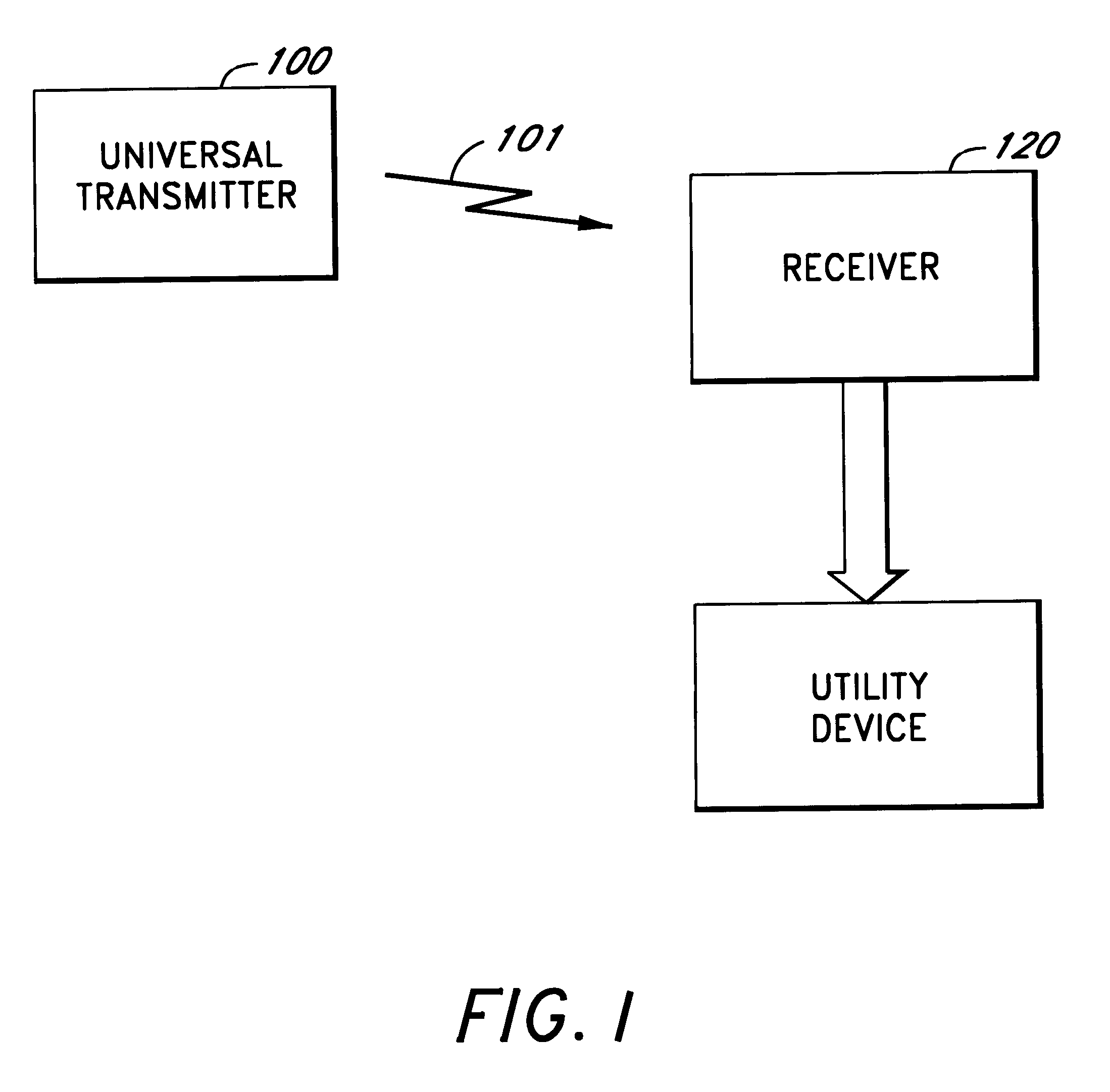
Referring now to the drawings, and in particular to FIG. 1, there is shown a block diagram of a typical transmitter-receiver system. In FIG. 1, transmitter 100 is any suitable transmitter capable of generating an electromagnetic wave represented by the arrow 101. The frequency of the signal 101 generated by transmitter ...


PUM


Abstract

A method and apparatus for providing a universal transmitter that can detect and emulate a transmission signal of a transmitter, the transmission signal having a corresponding transmission frequency and a corresponding modulation pattern. The universal transmitter comprises: a detection circuit that detects a frequency and a modulation pattern of a transmitted signal of a separate transmitter and a memory. A processor coupled to the detection circuit and the memory, stores a frequency value representative of the detected frequency and a plurality of value representative of the detected modulation pattern, in the memory. A transmitting circuit coupled to the processor, is operable to transmit an output signal having the frequency and the modulation pattern of the transmission signal.

Description

1. Field of the InventionThe invention is directed in general to remote control systems including transmitters and / or receivers which operate on a coded signal and, in particular, to a universal remote control transmitter that can acquire the transmission frequency and modulation pattern of another transmitter without a prior knowledge of these parameters.2. Background of the InventionTransmitter-receiver controller systems are widely used for remote control and / or actuation of devices or appliances such as garage door openers, gate openers, security systems, and the like. For example, most conventional garage door opener systems use a transmitter-receiver combination to selectively activate the drive source (i.e., motor) for opening or closing the door. The receiver is usually mounted adjacent to the motor and receives a coded signal (typically radio frequency) from the transmitter. The transmitter is typically carried in the vehicle by a user and selectively activated by the user ...

Claims


Application Information

Patent Timeline
IPC IPC(8): G08C19/28G08C19/16H04B1/02H04B1/034
CPCG08C19/28H04B1/0346G08C2201/92
Inventor TSUI, PHILIP Y. W.
Owner TSUI PHILIP Y W
Why Eureka
Try Eureka