System and method for terahertz imaging using a single terahertz detector

a terahertz imaging and detector array technology, applied in the field of imaging, can solve the problems of high cost, difficult and expensive to fabricate an array of thz detectors for a thz imaging system, and more pixels have better resolution, and achieve good spatial details and high resolution

Inactive Publication Date: 2005-06-21
PHILIP MORRIS USA INC
View PDF21 Cites 23 Cited by
  • Summary
  • Abstract
  • Description
  • Claims
  • Application Information

AI Technical Summary

Benefits of technology

[0008]The present invention solves the problems of the related art by providing a system and method for THz imaging that uses a single THz detector that detects an image of a large area and provides good spatial details (high resolution) without scanning the THz beam across the entire sample or vice versa.
[0010]In one aspect of the invention, the time-multiplexing technique, the THz beam passes through an object to be imaged, and a THz fiber bundle having a plurality of THz fibers collect the THz beam on the other side of the object and transmit the beams to a single THz detector. Each THz fiber imparts a different time delay to the beam traveling therein. Therefore, the spatial information, as represented by the physical location of the fibers, is converted into time information in the form of time delays. The amount of time delay through a THz fiber can be controlled in two ways: (1) by changing the refractive index n of the THz fiber; or (2) by changing the length l of the THz fiber. Knowing the distance each part of the imaging area must travel (hence the time it takes) before reaching the THz detector, one can recover the spatial information from the time data.
[0012]In another aspect of the invention, the pixel-modulation technique, each pixel is turned on / off with a distinct pattern from all of the other pixels. Even though there is a single THz detector, the THz energy emanating from each pixel can be identified because of the distinct on / off pattern of each pixel. To turn each pixel on and off, one variation of the pixel-modulation technique uses a series of masks. Each mask may have a set of holes corresponding to a set of pixels being in their ON states. Different masks may have different sets of pixels being ON. The masks may be mounted in front of or behind the object, on a translation stage. Each mask is moved into position (in front of or behind the object) and measurements are taken. Knowing the on / off pattern of each pixel, the measured data may be computer processed to obtain the THz data for each pixel. The modulation patterns for the pixels may be Hadamard matrix, S matrix, or random. This technique provides an increased signal-to-noise ratio as compared to using a single hole (i.e., a single pixel) and moving the hole location from one measurement to the next. Variations of this arrangement include using a spatial light modulator to turn the pixels on and off electronically, and using a micro-mirror array to turn the pixels on and off electronically. These variations eliminate the need for different masks and a translating stage.

Problems solved by technology

This is why a digital camera with more pixels has better resolution (e.g., a clearer and sharper picture) and costs more.
Unfortunately, it is very difficult and expensive to fabricate an array of THz detectors for a THz imaging system.

Method used


Image

  • System and method for terahertz imaging using a single terahertz detector
  • System and method for terahertz imaging using a single terahertz detector
  • System and method for terahertz imaging using a single terahertz detector

Examples


Embodiment Construction

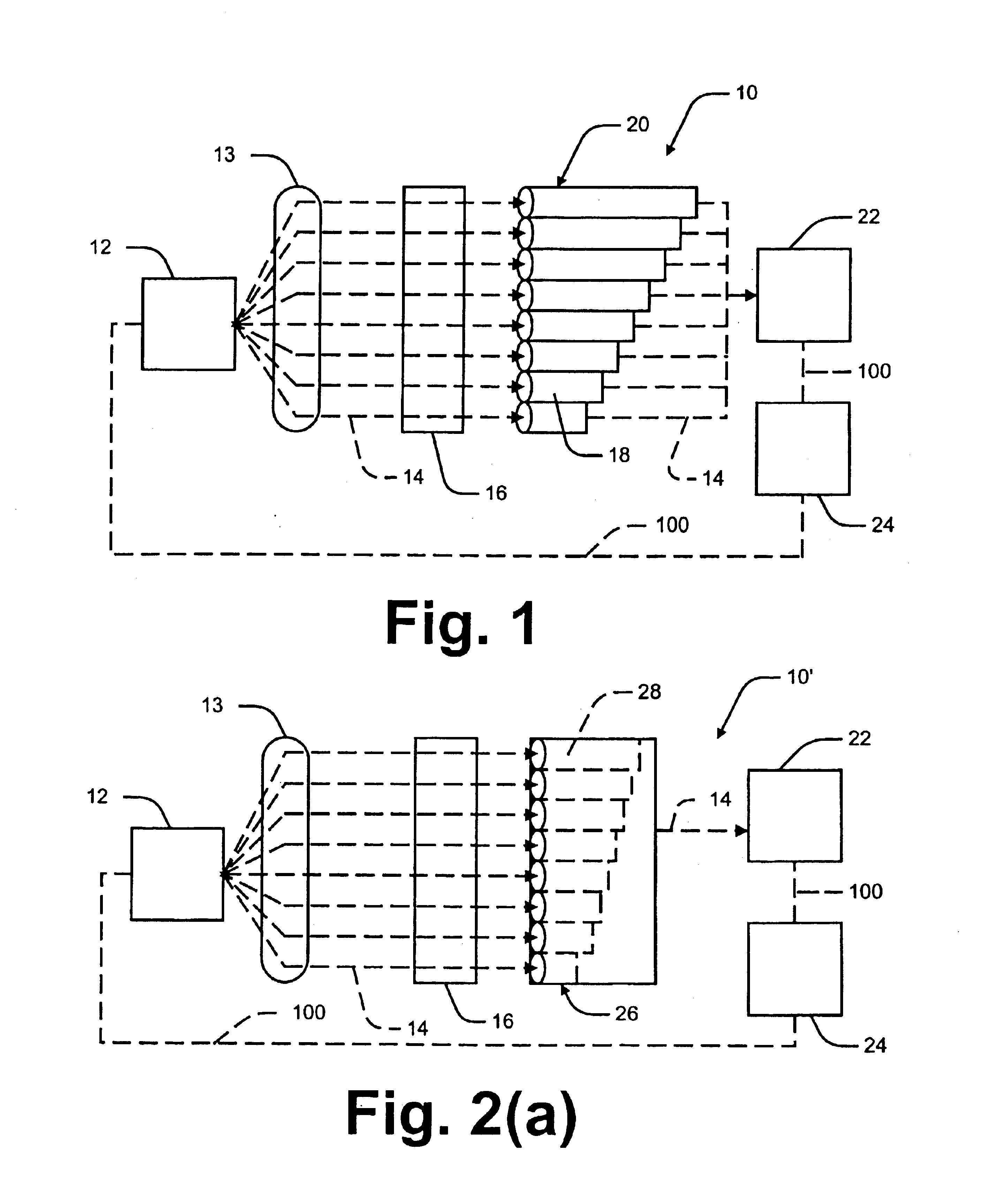
[0027]The following detailed description of the invention refers to the accompanying drawings. The same reference numbers in different drawings identify the same or similar elements. Also, the following detailed description does not limit the invention. Instead, the scope of the invention is defined by the appended claims and equivalents thereof.

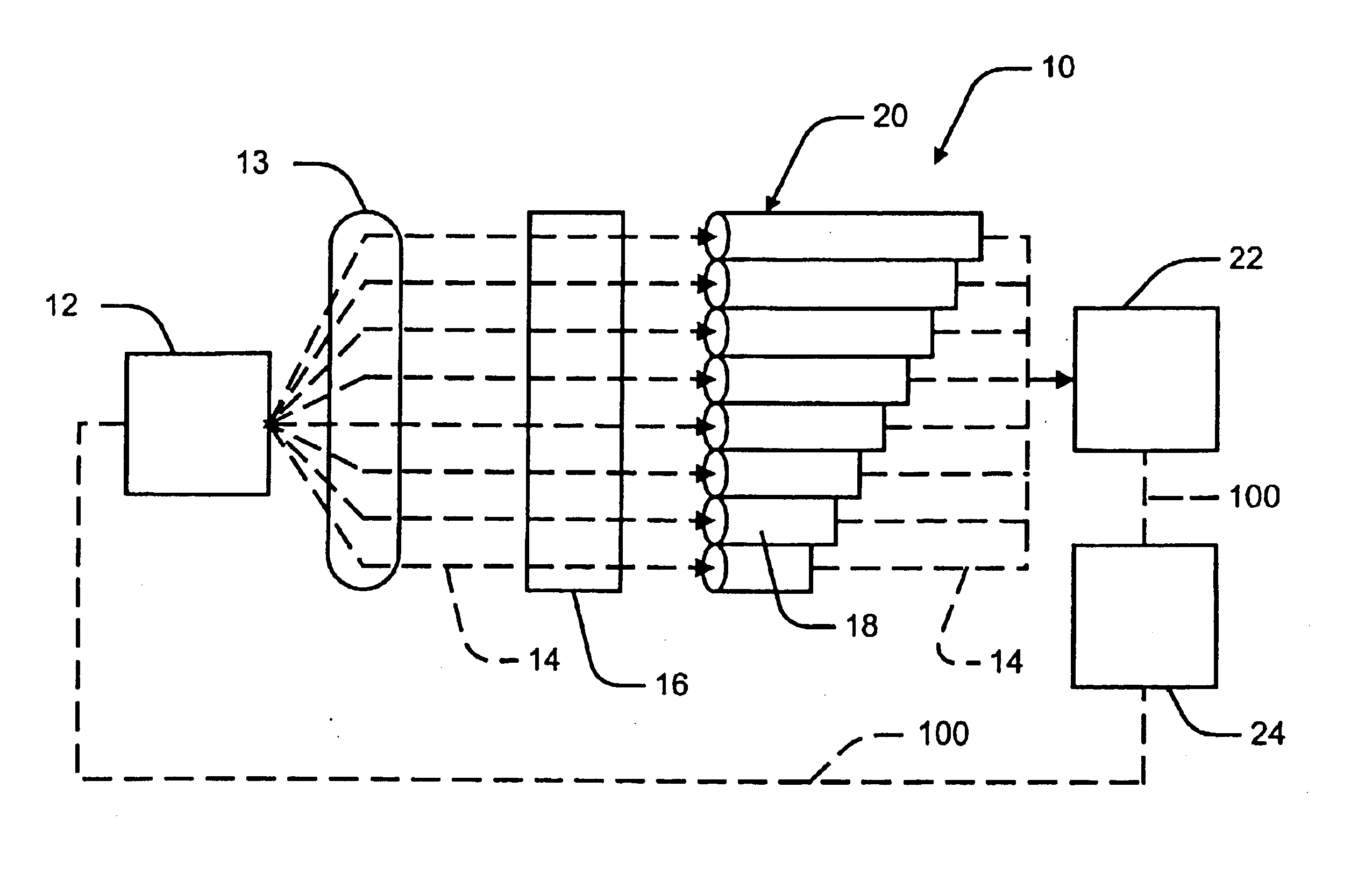
[0028]Referring now specifically to the drawings, a THz imaging system according to an embodiment of the present invention is illustrated in FIG. 1 and shown generally as reference numeral 10. The THz imaging system 10 has particular application in imaging any type of object. As used herein, the term “object” or “sample” encompasses any object or sample to be THz imaged. There are many potential commercial applications in which THz imaging may be utilized. Promising applications include industrial quality and process control, package inspection, moisture analysis, contamination measurements, and chemical analysis. Thus, the object and the an...


PUM

PropertyMeasurementUnit
diameteraaaaaaaaaa
diameteraaaaaaaaaa
sizeaaaaaaaaaa

Abstract

A system and method for THz imaging utilizing a single THz detector that detects an image of a large area and provides good spatial details (high resolution). In one aspect, the system can individually modulate a different pixel of an image. The system could be a series of masks. Each mask may include holes that may be turned on / off with a distinct pattern from all of the other holes. Once the data for each mask has been received, the data for each hole may be extracted according to its modulation pattern. Another modulation system may include a micro-mirror array that deflects the THz signal towards or away from the THz detector.

Description

CROSS REFERENCE TO RELATED APPLICATIONS[0001]The present application is a continuation-in-part of application Ser. No. 10 / 365,029, filed Feb. 12, 2003, the disclosure of which being incorporated by reference herein in its entirety.BACKGROUND OF THE INVENTION[0002]A. Field of the Invention[0003]The present invention relates generally to imaging in the terahertz (THz) frequency range, and, more particularly to a system and method for terahertz imaging that utilizes a single terahertz detector.[0004]B. Description of the Related Art[0005]A terahertz (“THz”) detector or receiver detects electromagnetic energy or radiation with frequencies in the terahertz range (fractions to tens of terahertz, where terahertz=1012 Hertz). A typical THz system consists of a THz transmitter and a THz detector. The transmitter transmits a THz beam that passes through or reflects from an object under examination. The THz detector detects the THz energy that passes through or reflects from the object, and re...

Claims


Application Information

Patent Timeline
Patent Type & Authority Patents(United States)
IPC IPC(8): G01N21/31G01N21/35
CPCG01N21/3581
Inventor TRAN, PHUC G.SHAFER, KENNETH H.
Owner PHILIP MORRIS USA INC
Why Eureka
Try Eureka