

Partial boiling in mini and micro-channels
a microchannel and partial boiling technology, applied in the direction of indirect heat exchangers, conduit assemblies of stationary plates, lighting and heating apparatus, etc., to achieve the effect of fewer bubbles and increased nucleation site density
- Summary
- Abstract
- Description
- Claims
- Application Information
AI Technical Summary
Benefits of technology
Problems solved by technology
Method used
Image

Examples
example 2
Distributed Partial Boiling in Micro-Channels
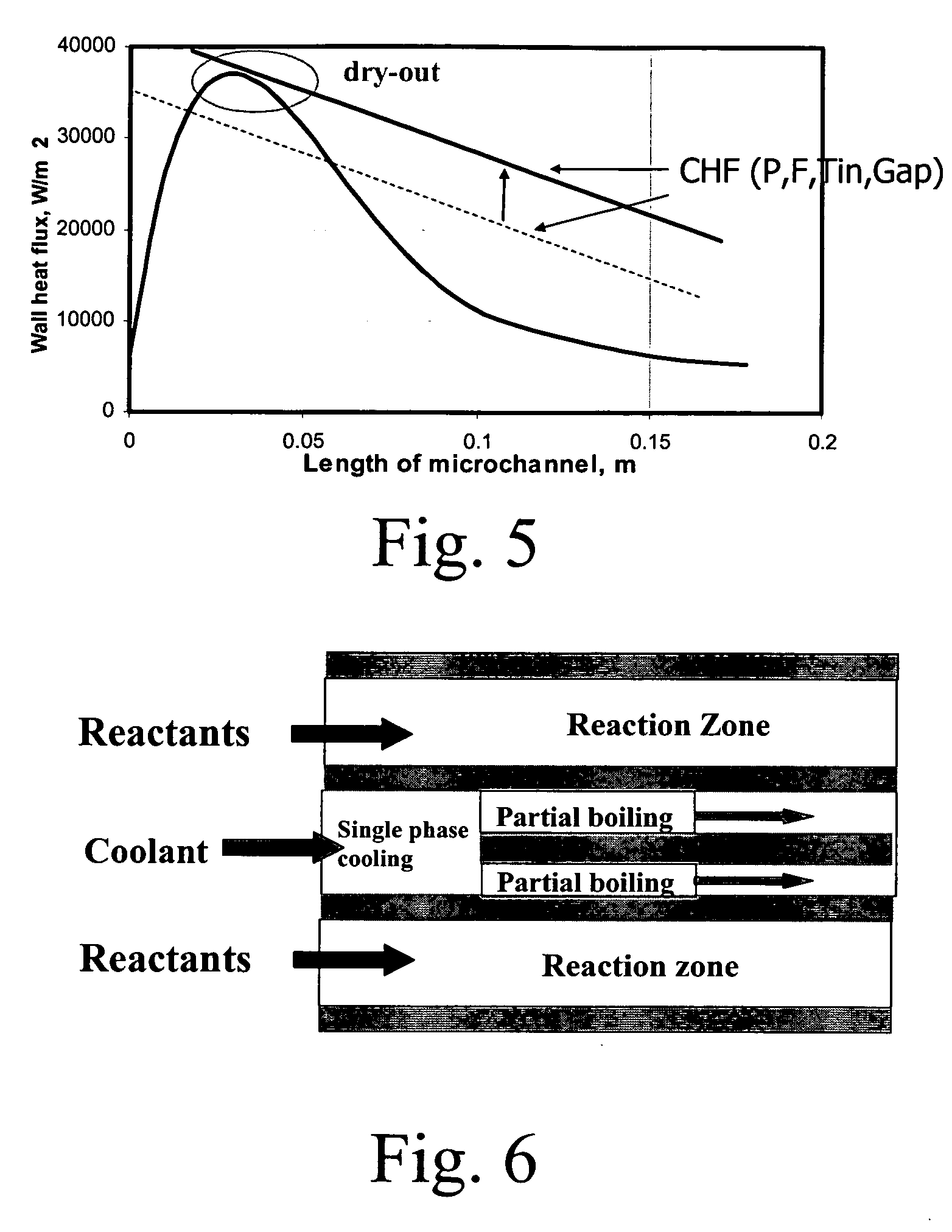
[0227] Partial boiling heat transfer in microchannels is integrated with microchannel reactors to conduct exothermic reactions. The cooling channels can be arranged in various connection patterns to efficiently remove the reaction heat. From the partial boiling curve, the heat flux has a large positive gradient after the single phase cooling section. From the process side where exothermic chemical reactions take place, the heat flux peak. typically occurs shortly after the beginning of the reaction zone. Its exact location is determined by reactant flow rate, the reactor dimension and the characteristics of the catalyst packed bed if the catalyst is used in the reactor. The typical heat flux curve from the process side shows that it peaks near the beginning the reactor. By designing the cooling channels with various types of connections, the heat flux curves from both process side and the cooling side can be aligned so that the partial b...
example 3
Partial Boiling in Micro-channel
[0232] A stainless steel device was fabricated to test partial boiling in micro-channels. The device was made by welding two stainless steel plates with milled micro-features that on assembly made micro-channels. Stainless steel plate 1 combined with stainless steel plate 2 to produce micro-channel flow paths. The total length of the plates and hence the micro-channels was 60 cm. The total width of the plates was 1.5(3.8 cm). The nominal thickness of both the stainless steel plates is 5 / 16 (8 mm). A chamfer was made at the outer edge of the plates to facilitate welding of the plates.
[0233] The micro-channels formed by combination of the two plates had cross-sectional dimension 0.030×0.018as shown in FIG. 1. The length to hydraulic diameter ratio was 1067. The micro-channels were separated by a metal wall of thickness 0.018. A total of 14 such micro-channels were formed. Holes were drilled in the stainless steel plates along the length of the micro-c...
example 4
[0246] Partial boiling heat transfer is applied to vinyl acetate monomer (VAM) production in micro-channels. The micro-channels by combination of the plates had cross-sectional dimension 0.05 mm×1.3 cm. The gap on the reaction side is 1 mm and on the coolant side is 1 mm. On the reaction side, a mixture of ethylene (C2H4), acid gas (CH3COOH) and oxygen (O2) is fed at temperature 160 C and pressure 8 atm. The micro-channel is packed with micro-pellet catalyst with a void fraction around 0.4.
[0247] The VAM producing reaction release heat into the packed bed and then the heat conducts through the channel walls to the surface on the coolant side, where the coolant vaporates. The coolant used in this example is water. At the beginning of the catalyst bed, the reactants are at the highest concentration level and the reaction rate is at the maximum. This leads to the asymmetrical temperature profile along the catalyst bed. Accordingly, the heat flux profile on the channel wall (FIG. 19) a...
PUM
| Property | Measurement | Unit |
|---|---|---|
| length | aaaaa | aaaaa |
| shear stress | aaaaa | aaaaa |
| length | aaaaa | aaaaa |
Abstract
Description
Claims
Application Information