Motor

a brushless motor and motor body technology, applied in the field of motors, can solve the problem of becoming difficult to connect wires to terminals, and achieve the effect of preferable connection workability

Active Publication Date: 2007-12-06
NIPPON DENSAN CORP
View PDF16 Cites 56 Cited by
  • Summary
  • Abstract
  • Description
  • Claims
  • Application Information

AI Technical Summary

Benefits of technology

[0018]With this unique configuration, the first terminals and the second terminals are not arranged in an axially overlapping manner, w...

Problems solved by technology

With a reduced space between adjacent terminals, it...

Method used


Image

  • Motor
  • Motor
  • Motor

Examples


Embodiment Construction

[0029]In the following description, when positional relationships among and orientations of the different components are described as being such as top / bottom, up / down or left / right, positional relationships and orientations that are in the drawings are indicated, and positional relationships among and orientations of the components once having been assembled into an actual device are not indicated. Meanwhile, in the following description, an axial direction indicates a direction parallel to a rotation axis, and a radial direction indicates a direction perpendicular to the rotation axis.

General Structure of Motor

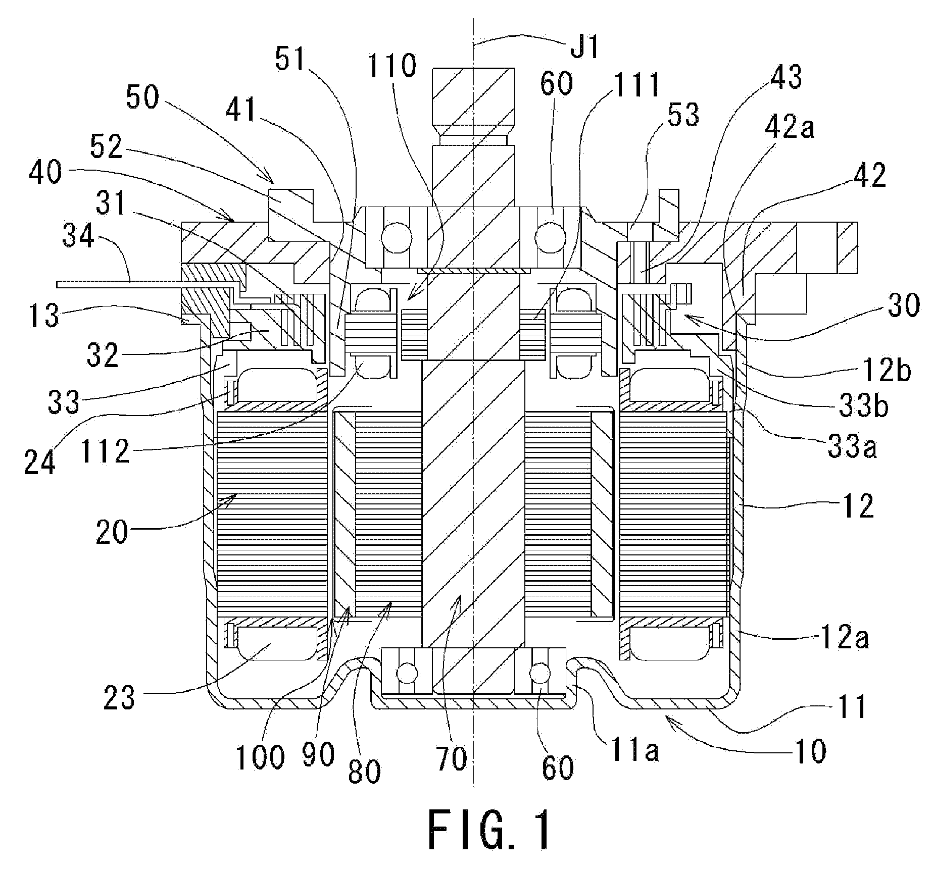
[0030]With reference to FIG. 1, a structure of a motor according to a preferred embodiment of the present invention will be described. FIG. 1 is a view illustrating a cross section of the motor along a center axis J1.

[0031]As illustrated in FIG. 1, a housing 10 of the motor includes a cylindrical portion 12 centered on the center axis J1 and a base 11 closing a lower side of...


PUM

PropertyMeasurementUnit
Shapeaaaaaaaaaa
Depthaaaaaaaaaa

Abstract

A motor includes a stator including a core back having a circular or substantially circular shape, a plurality of tooth portions extending radially inwardly from the core back, a plurality of insulators covering the tooth portions, a plurality of coils formed by winding wires around the tooth portions via the insulators. The motor also includes a bus bar arranged axially above the stator. The bus bar supports a first conductor plate having a plurality of first terminals to which first end portions of the wires from each phases of the coils are connected. The insulators include a guiding groove and support therein the second conductor plate to which second end portions of the wires are connected. Through the second conductor plate, the second end portions of the wires are connected to the neutral point.

Description

BACKGROUND OF THE INVENTION[0001]1. Field of the Invention[0002]The present invention generally relates to a motor, in particular to a brushless motor having a stator on which an insulator is arranged.[0003]2. Background of the Related Art[0004]Conventionally, a brushless motor (hereinafter simply referred to as a motor) used for an electric powered power-steering system includes a bus bar having a connector to which a coil arranged on a stator is connected. The stator is centered on a center axis and is formed by axially laminating a plurality of steel plates. The stator includes a core back having a circular shape centered on the center axis and teeth extending radially inwardly from an inner circular surface of the core back. The teeth are arranged in a circumferentially spaced manner from each other. A set of insulators, each of which has a U-shape, are attached to each of the teeth. One of the insulators is attached to each of the teeth from an axially upper side thereof, and t...

Claims


Application Information

Patent Timeline
IPC IPC(8): H02K11/00H02K3/46
CPCH02K3/522H02K11/0031Y10T29/49009H02K2203/09H02K2203/12H02K29/12H02K11/225
Inventor HAGA, HIDEHIROYAMASHITA, YOSHIAKIKATAOKA, NAKABA
Owner NIPPON DENSAN CORP
Why Eureka
Try Eureka