Electrode for a charged particle beam lens

a technology of electrostatic lens and electrode, which is applied in the direction of beam deviation/focusing by electric/magnetic means, instruments, mass spectrometers, etc., can solve the problems of deterioration of the optical characteristics of the lens, and achieve the effect of reducing the space between the lens including the electrode and the obj

Inactive Publication Date: 2014-04-03
CANON KK
View PDF3 Cites 12 Cited by
  • Summary
  • Abstract
  • Description
  • Claims
  • Application Information

AI Technical Summary

Benefits of technology

[0007]According to the electrode of the present invention, the opening contour of the first region is included in the opening contour of the second region when viewed in the optical axis direction, and hence, a scattered substance, or the like, of an object is blocked by the first region so as to hardly reach the second region and a region closer to a charged particle source with respect to the second region. Therefore, it is possible to realize the electrode in which the scattered substance or the evaporated substance of the object can hardly reach the second region and a region closer to the charged particle source with respect to the second region. In addition, it is not necessary to dispose an additional shield plate, or the like, and hence, the space between the lens including the electrode and the object can be decreased.
[0008]Further features of die present invention will become apparent from the following description of exemplary embodiments with reference to the attached drawings,

Problems solved by technology

This adhesion of the resist, or the like, causes deterioration of optical characteristics of the lens, and is apt to be an obstacle for long-term use.

Method used


Image

  • Electrode for a charged particle beam lens
  • Electrode for a charged particle beam lens
  • Electrode for a charged particle beam lens

Examples


first embodiment

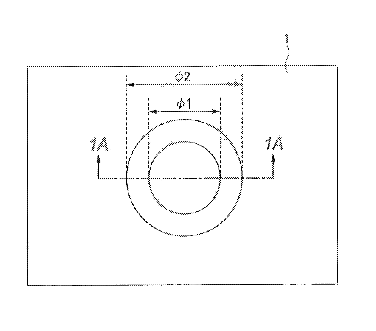
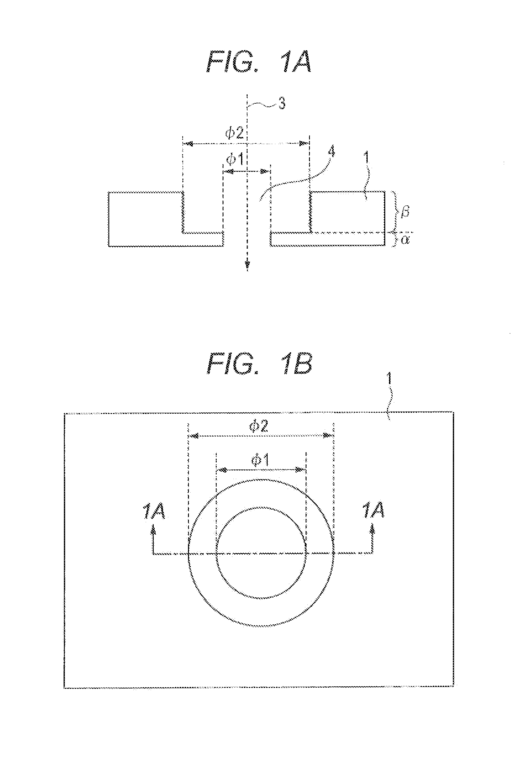
[0016]With reference to FIGS. 1A and 1B and FIGS. 5A to 5C, a first embodiment of she present invention is described, FIG. 1B is a schematic top view of an electrode closest to an object to be irradiated by a charged particle beam, which is used for a charged particle beam objective lens, FIG. 1A is a schematic cross-sectional view taken along the line 1A-1A of FIG. 1B.

[0017]As illustrated in FIG. 1A, in this embodiment, an electrode 1 closest to the object to be irradiated by the charged particle beam is a flat plate having an optical axis 3 as the normal, and has a through hole 4, This through hole 4 has a circular cross section, which includes a first region α having a first internal diameter φ1 and a second region β having a second internal diameter φ2. The relationship between those internal diameters is φ2>φ1. The second region β having the relatively larger internal diameter is positioned on the side closer to a charged particle source as a light source (not shown), namely, a...

second embodiment

[0027]With reference to FIG. 2A, a second embodiment of the present invention is described. This embodiment is a charged particle beam objective lens using an electrode described in the first embodiment. A portion having the same function as that of the first embodiment is denoted by the same reference numeral or symbol, and an overlapping description thereof is omitted.

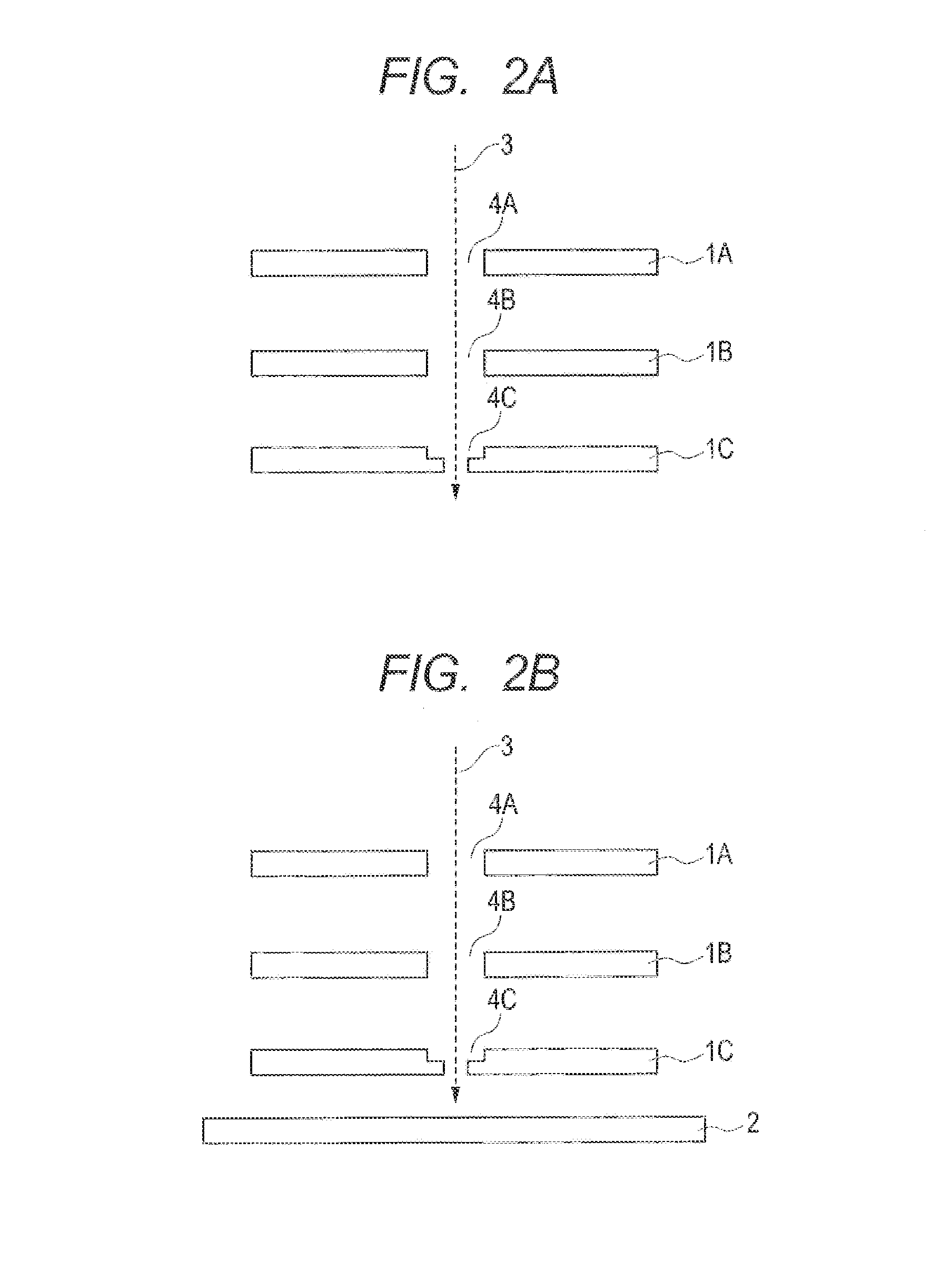
[0028]As illustrated in FIG. 2A, the charged particle beam objective lens of this embodiment includes three electrodes 1A, 1B, and 1C. The three electrodes are flat plates having the optical axis 3 as the normal and are electrically insulated from each other. The three electrodes have through holes 4A, 4B, and 4C, respectively, which transmit the charged panicles emitted from the charged particle source (not shown). The centers of the through holes 4A, 4B, and 4C are aligned along the optical axis direction. If each electrode has multiple through holes, corresponding through holes of the multiple electrodes are align...

third embodiment

[0035]With reference to FIGS. 2B, 3A, and 3B, a third embodiment of the present invention is described. This embodiment shows an exemplary positional relationship between a shape of the electrode closest to the sample to be irradiated with the charged particle beam and the sample in a case wherein the charged particle beam objective lens is applied to the charged particle beam exposure equipment. A portion having the same function as the above-mentioned embodiments is denoted by the same reference numeral or symbol, and an overlapping description thereof is omitted.

[0036]FIG. 2B is a schematic cross-sectional view of the charged particle beam objective lens and its vicinity of the charged particle beam exposure equipment according to this embodiment. As illustrated in FIG. 2B, in the charged particle beam exposure equipment of this embodiment, a sample 2 is irradiated with, the charged particle beam passing through the through holes 4A, 4B, and 4C of the electrodes 1A, 1B, and 1C to...


PUM


Abstract

An electrode to be used for an electrostatic charged particle beam lens includes at least one through hole. The at least one through hole includes a first region having a first opening contour and a second region having a second opening contour to be positioned on an upstream side of a charged particle beam with respect to the first region, The first opening contour is included in the second opening contour when viewed in an optical axis direction.

Description

[0001]This application claims the benefit of Japanese Patent Application No. 2011-139965, filed Jun. 23, 2011, which is hereby incorporated by reference herein in its entirety.TECHNICAL FIELD[0002]The present invention relates to a charged particle beam optical system used for charged particle beam exposure equipment, such as electron beam exposure equipment or ion beam exposure equipment, which are used for exposure of a semiconductor integrated circuit, or the like. In particular, the present invention relates to an electrode for an electrostatic lens (typically, an electrode for an electrostatic objective lens).BACKGROUND ART[0003]As exposure equipment for exposing patterns in which fine patterns having a width of 0.1 micrometers or less are packed at high density, the electron beam exposure equipment is quite prospective. In particular, an electron beam exposure equipment that is capable of patterning with multiple electron beams, simultaneously, without using a photomask is qui...

Claims


Application Information

Patent Timeline
Patent Type & Authority Applications(United States)
IPC IPC(8): H01J37/12
CPCH01J37/12B82Y10/00B82Y40/00H01J37/3177
Inventor NOMURA, KAZUSHI
Owner CANON KK
Why Eureka
Try Eureka