
Assembled packing case

a packing case and assembly technology, applied in the field of packaging techniques, can solve the problems of occupying more space, occupying more space, and requiring plenty of cushioning material, etc., and achieves the effects of reducing the cost of packaging

Inactive Publication Date: 2014-07-24
TCL CHINA STAR OPTOELECTRONICS TECH CO LTD
View PDF9 Cites 12 Cited by
  • Summary
  • Abstract
  • Description
  • Claims
  • Application Information

AI Technical Summary

Benefits of technology

The present invention provides a packing case with a simple and compact structure and low cost. The packing case is formed by connected structures without thread, riveting, or welding, which make it perfectly fitting the packed objects. It can protect them and be suitable for packed objects with different sizes by changing a bottom component. The cost can be greatly reduced by reusing corner components.

Problems solved by technology

However, this way for packing glass plate costs a lot for it needs plenty of cushioning material.
Furthermore, the overall volume will be big, and it will take up more space when multi-layer glass plates are packed together because cushioning material needs to be filled between each two glass plates.

Method used


Image

  • Assembled packing case
  • Assembled packing case
  • Assembled packing case

Examples


Embodiment Construction

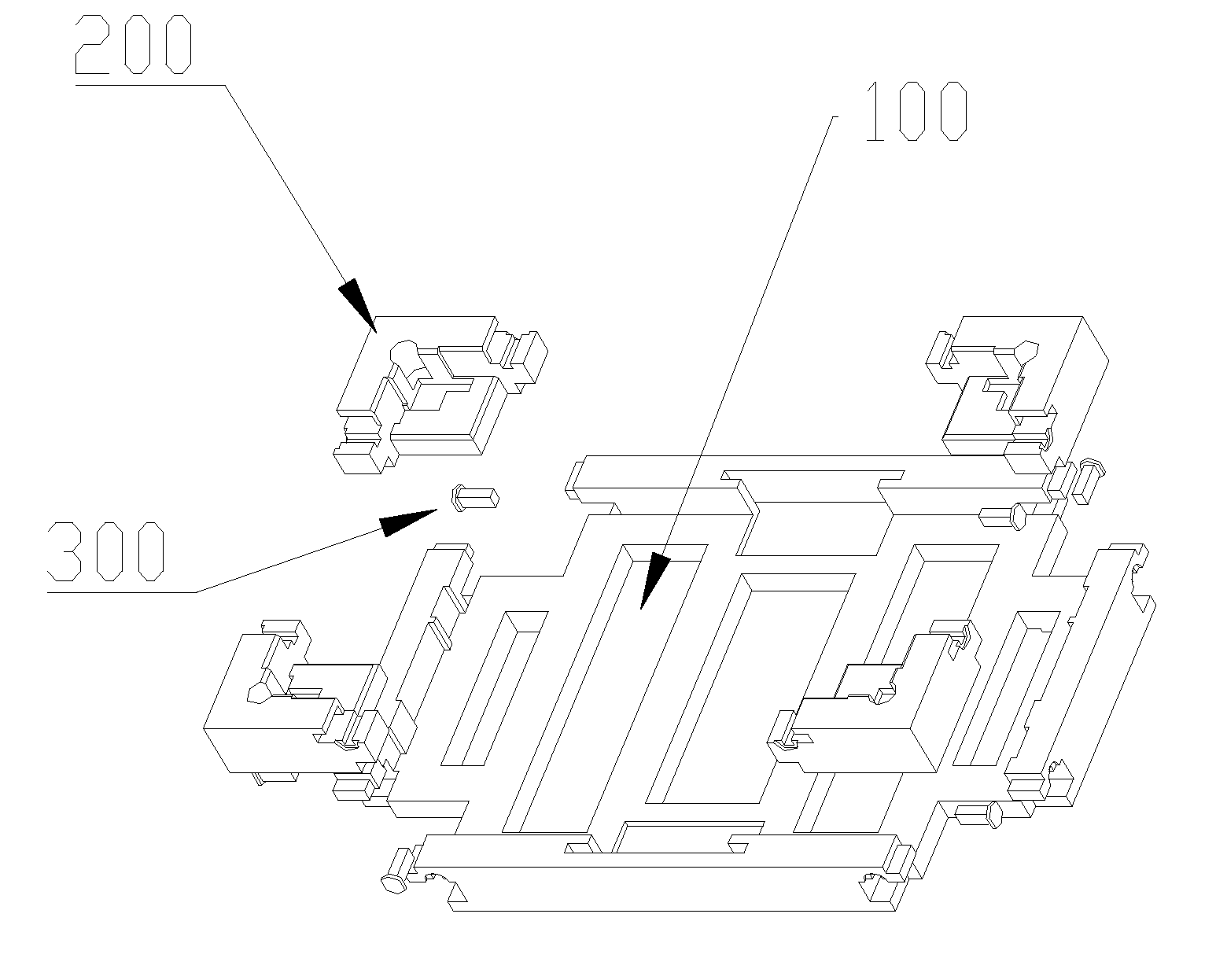
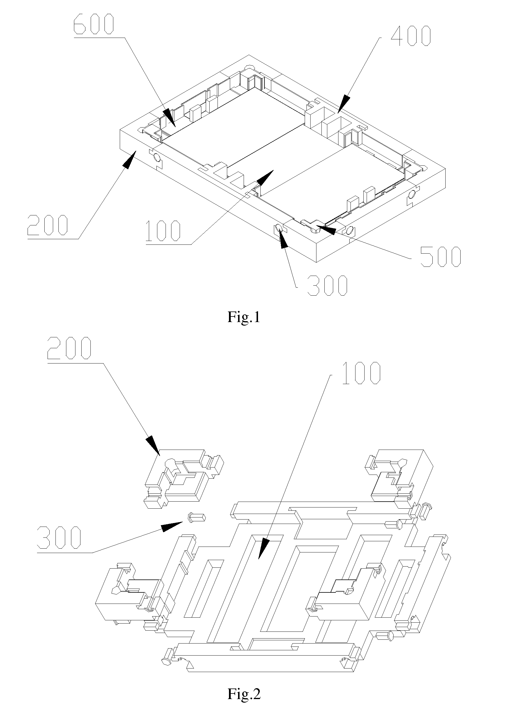
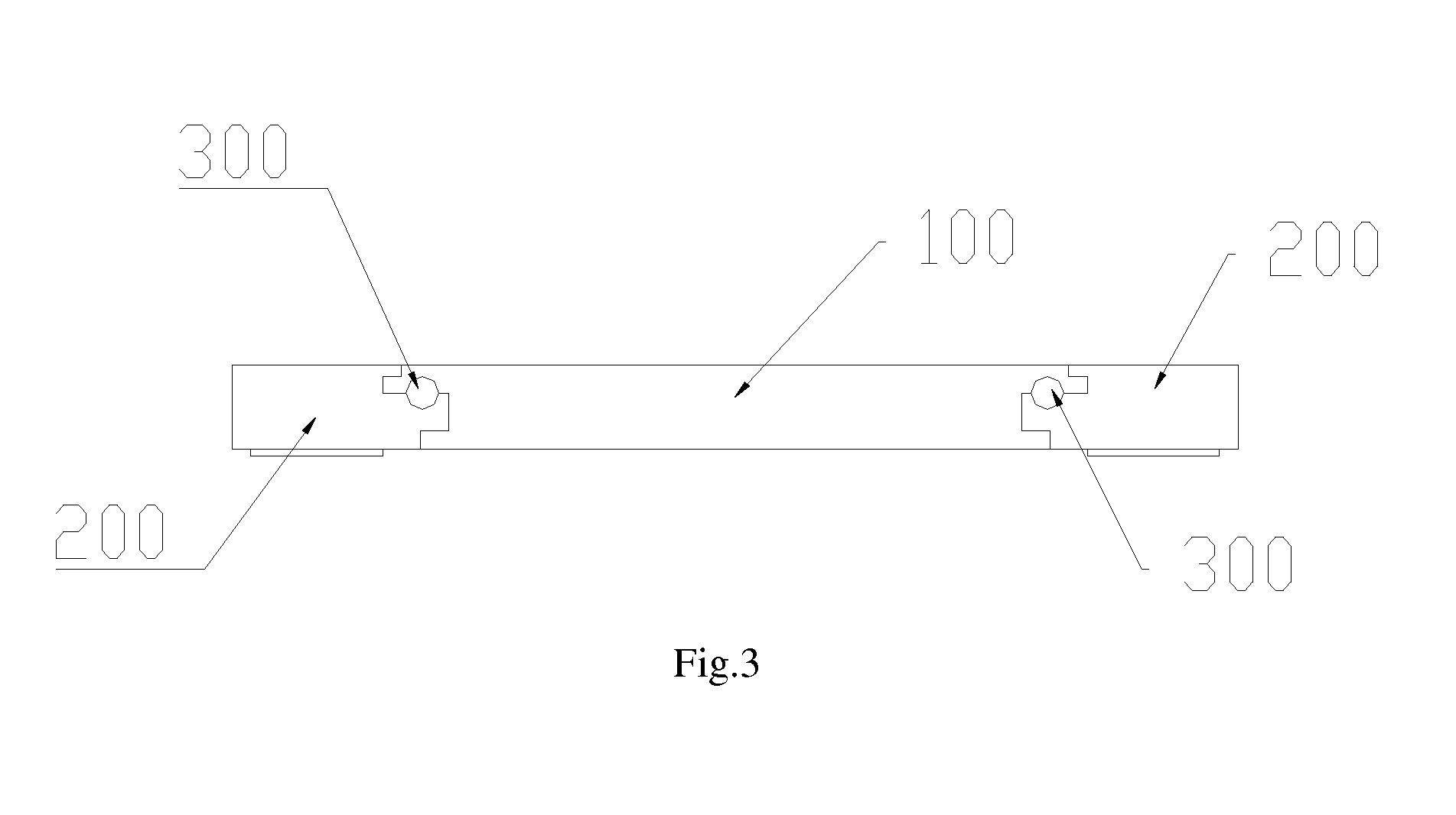
[0024]FIG. 1 is a structural schematic drawing of a preferred embodiment of the assembled packing case of the present invention, and FIG. 2 is an explosive view of the assembled packing case of this embodiment. In this embodiment, the assembled packing case comprises a bottom component 100 and corner components 200 that clamped at the corner of the bottom component 100. Limiting holes are set at the clamping positions of the bottom component 100 and the corner components 200, and the assembled packing case further comprises fasteners 300 that insert into the limiting holes, when the fasteners 300 are inserted, the relative position between the bottom component 100 and the corner components 200 will be limited. The underside of the bottom component 100 is cruciform, and the shape of the corner components 200 is consistent with the shape of the four corners of the corner component 200, a cuboid case body with a hold space will be formed and various objects can be placed when the botto...


PUM


Abstract

The present invention relates to an assembled packing case, which comprises a bottom component with a cruciform underside, and corner components clamped at the vacant corner of the bottom component; limiting holes are set at the clamping positions of the bottom component and the corner components; and further comprises fasteners inserting into the limiting holes to limit the relative position between the bottom component and the corner components; the bottom component and the corner component are set as mortise and tenon structures at their junctions; the bottom component and the corner components joggle into a packing case by the mortise and tenon structures. The structure of the assembled packing case is simple and the cost is low.

Description

FIELD OF THE INVENTION[0001]The present invention relates to packing technique, and more particularly to an assembled packing case.BACKGROUND OF THE INVENTION[0002]Different kinds of glass plate are needed during the production of the liquid crystal display module, and the glass plate must be protected with special packing technique to avoid damage of the glass plate due to the collision, vibration, friction during the transportation because the glass plate is a kind of fragile and vulnerable material. Generally, the existing way for packing glass plate is filling cushioning material, for example, expanded polypropylene plastic material (expanded polypropylene, EPP), between the glass plates to avoid the damage of the glass plate. However, this way for packing glass plate costs a lot for it needs plenty of cushioning material. Furthermore, the overall volume will be big, and it will take up more space when multi-layer glass plates are packed together because cushioning material need...

Claims


Application Information

Patent Timeline
Patent Type & Authority Applications(United States)
IPC IPC(8): B65D81/05
CPCB65D81/056B65D11/10B65D85/48
Inventor KUO, YI-CHENGCHEN, SHIH HSIANGLI, JIAXIN
Owner TCL CHINA STAR OPTOELECTRONICS TECH CO LTD
Learn More