Ultrasound focusing using a cross-point switch matrix

a cross-point switch and ultrasonic technology, applied in the field of ultrasonic systems, can solve the problems of reducing intensity level, affecting treatment efficiency, beam aberration, etc., and achieve the effects of reducing temperature inhomogeneity, reducing or increasing peak pressure, and reducing profile distortion

Active Publication Date: 2018-12-20
INSIGHTEC
View PDF5 Cites 23 Cited by
  • Summary
  • Abstract
  • Description
  • Claims
  • Application Information

AI Technical Summary

Benefits of technology

[0016]In various embodiments, the system includes a magnetic resonance (MR) unit for monitoring a temperature of the target, and the controller is configured to adjust the duty cycle in response to the monitored temperature. In addition, the controller may be further configured to responsively operate the switch matrix to energize or ground selected ones of the transducer elements of each of the sets so as to reduce temperature inhomogeneities in an ultrasound beam path zone and/or the target detected by the MR monitoring. In some embodiments, the MR unit is further configured to monitor a location and profile of the focus, and the controller is configured to responsively operate the switch matrix to energize or ground the selected ones of the transducer elements of each of the sets so as to reduce profile distortion of the focus.
[0017]The system may further include a cavitation detector for detecting cavitat

Problems solved by technology

As described above, as an acoustic beam passes through the tissue located between the transducer elements and target region, beam aberration may occu

Method used


Image

  • Ultrasound focusing using a cross-point switch matrix
  • Ultrasound focusing using a cross-point switch matrix
  • Ultrasound focusing using a cross-point switch matrix

Examples


Embodiment Construction

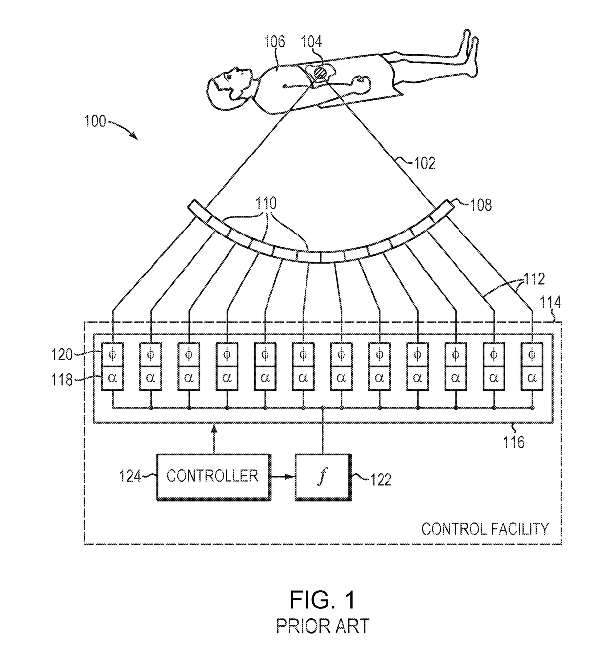
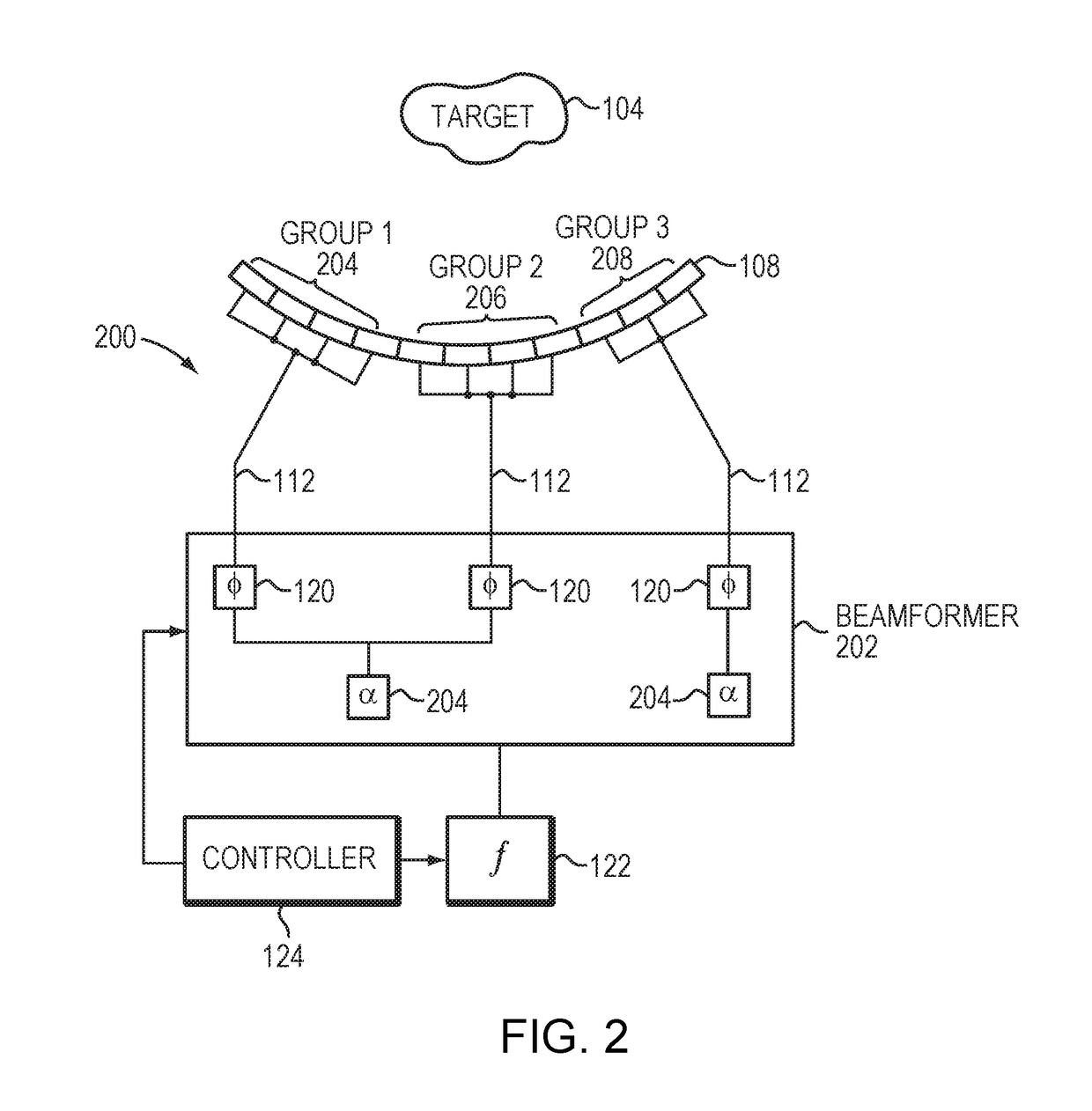
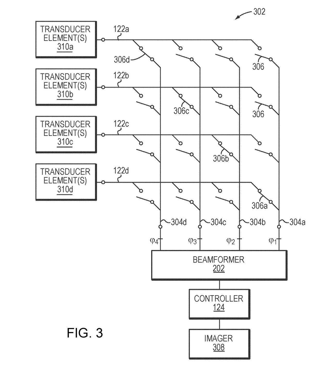
[0035]Phased-array ultrasound transducers in accordance with various embodiments of the invention typically include a large number (e.g., hundreds and up to thousands) of individual transducer elements whose linear dimensions in general are no greater than the wavelength of the acoustic waves generated during operation. Using small transducer elements results in increased steerability of the acoustic beam in three-dimensions—i.e., steering of both the depth of focus and the lateral focus position, over a large volume. For example, with transducer element dimensions of no more than half a wavelength, the steering angle (i.e., the maximum angle with respect to the normal of the transducer surface that can be achieved) in each direction is ±π / 2, which facilitates covering a complete hemisphere. In certain embodiments, the transducer elements are of uniform size and shape and are evenly arranged (e.g., in a tiled fashion) so as to form an isotropic array. In other embodiments, the trans...


PUM


Abstract

A system for delivering ultrasound energy to an internal anatomical target includes an ultrasound transducer having multiple transducer elements collectively operable as a phased array; multiple driver circuits, each being connected to at least one of the transducer elements; multiple phase circuits; a switch matrix selectably coupling the driver circuits to the phase circuits; and a controller configured for (i) receiving as input a target average intensity level and/or an energy level energy to be applied to the target and/or a temperature level in target, (ii) identifying multiple sets of the transducer elements, each of the sets corresponding to multiple transducer elements for shaping and/or focusing, as a phased array, ultrasound energy at the target across tissue intervening between the target and the ultrasound transducer, and (iii) sequentially operating the transducer-element sets to apply and maintain the target average energy level at the target. In various embodiments, the controller operates each of the transducer element sets in accordance with a pulse-width modulation pattern having a duty cycle selected to achieve the target average intensity level, energy level, and/or temperature level at the target in accordance with a time constant of the target tissue.

Description

FIELD OF THE INVENTION[0001]The field of the invention relates generally to ultrasound systems and, more particularly, to systems and methods for facilitating ultrasound focusing using a cross-point switch matrix.BACKGROUND[0002]Focused ultrasound (i.e., acoustic waves having a frequency greater than about 20 kiloHertz) can be used to image internal body tissues or, at high intensity, to generate thermal ablation energy to treat tissue such as tumors or disrupt vasculature to deliver drugs. By way of illustration, FIG. 1 is a simplified schematic representation of an exemplary focused ultrasound system 100 used to generate and deliver a focused acoustic energy beam 102 to a targeted tissue 104 in a patient 106. The system 100 employs an ultrasound transducer 108 that is geometrically shaped and physically positioned relative to the patient 106 in order to focus the ultrasonic energy beam 102 at a three-dimensional focal zone located within the targeted tissue 104. The system can sha...

Claims


Application Information

Patent Timeline
IPC IPC(8): A61B8/00A61B5/01A61B5/055A61N7/02G01S7/52
CPCA61B8/4488A61B5/01A61B5/055A61N7/02G01S7/52022G01S7/52085A61N2007/0052A61N2007/0078A61B2017/22027A61B2017/22008A61B17/22004A61N2007/0039A61N2007/027A61N2007/0004B06B1/0292B06B1/0622A61B2017/00084A61B2017/00154A61B2017/22014A61B2018/00708A61B2018/00726A61B2018/0075A61B2018/00791A61N2007/0095A61B2090/374A61B8/5215G16H50/20
Inventor VORTMAN, KOBIVITEK, SHUKILEVY
Owner INSIGHTEC
Why Eureka
Try Eureka