Rapid-chirps-fmcw radar

a frequency difference and radar technology, applied in the field of radars, can solve the problems of not being able to determine unambiguously which peak, not yet being able to determine the distance and the relative velocity of the frequency difference on a single ramp, and achieving a good approximate value

Active Publication Date: 2015-11-19
ROBERT BOSCH GMBH
View PDF7 Cites 24 Cited by
  • Summary
  • Abstract
  • Description
  • Claims
  • Application Information

AI Technical Summary

Benefits of technology

[0014]The present invention makes use of the circumstance that the phase difference of the intermediate frequency signals for the two frequency-offset ramps is almost independent of the relative velocity of the object when there is a short time interval between the two ramps and therefore it supplies a good approximate value for the object di

Problems solved by technology

The measurement of the frequency difference on a single ramp therefore does not yet allow a determination of the distance and the relative velocity, but instead yields only a linear relationship between these variables.
However, when several objects are located simultaneously, the frequency spectrum of the intermediate frequency signal contains multiple peaks on each ramp, one for each object, and when the peaks on different ramps are compared, it is no longer possible to ascertain unambiguously which peak belongs to which object.
However, with an increase in the number of simultaneously located objects, there is a drastic inc

Method used


Image

  • Rapid-chirps-fmcw radar
  • Rapid-chirps-fmcw radar
  • Rapid-chirps-fmcw radar

Examples


Embodiment Construction

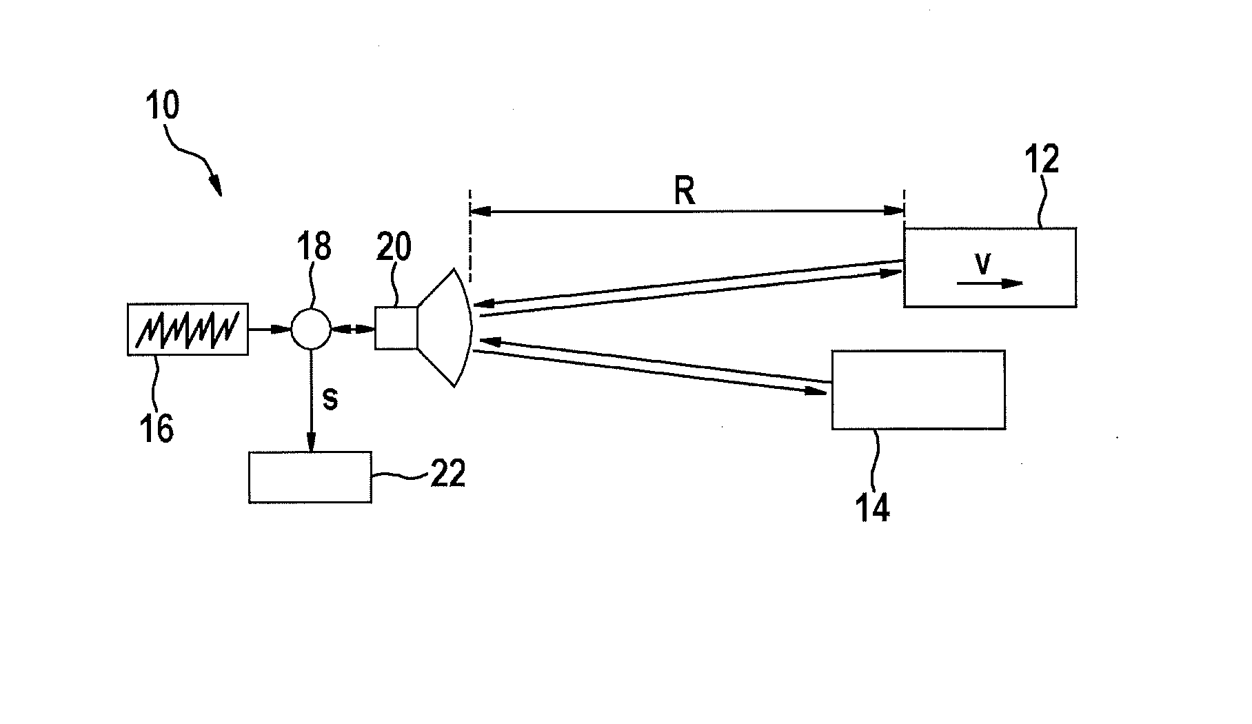
[0022]FIG. 1 shows as a simplified block diagram of an FMCW radar sensor 10, which is installed at the front of a motor vehicle, for example, and serves to measure distances R and relative velocities v of objects 12, 14, for example, of preceding vehicles. Radar sensor 10 has a voltage-controlled oscillator 16, which supplies a frequency-modulated transmission signal via a mixer 18 to a transceiver unit 20, which emits the signal in the direction toward objects 12, 14. The signal reflected on the objects is received by transceiver unit 20 and is mixed with a component of the transmission signal in mixer 18. An intermediate frequency signal s, which is analyzed further in an electronic evaluation and control unit 22, is obtained in this way.

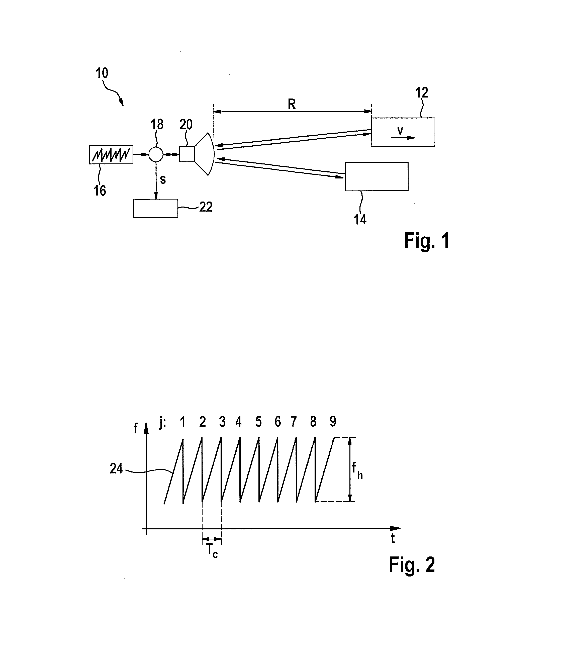
[0023]FIG. 2 shows an example of a modulation scheme of the transmission signal supplied by oscillator 16. Frequency f of the transmission signal is plotted here as a function of time t. The frequency is modulated in the form of successive identic...


PUM


Abstract

Method for determining distances and relative velocities of simultaneously located objects using an FMCW radar, in which the frequency of a transmission signal is modulated in the form of periodically recurring ramps, the transmission signal is mixed with a received signal to form an intermediate frequency signal and, for determining the distance and/or the relative velocity of the objects, the change in the phase of the intermediate frequency signal is evaluated from one ramp to the next characterized in that the modulation pattern includes at least two ramps, which differ only by a fixed frequency offset and follow one another in a certain time interval, and an unambiguous approximate value is calculated for the object distance on the basis of the phase difference φ1−φ2 of the intermediate frequency signals for these two ramps.

Description

FIELD OF THE INVENTION[0001]The present invention relates to a method for determining distances and relative velocities of multiple simultaneously located objects using an FMCW radar, in which the frequency of a transmission signal is modulated in the form of periodically recurring ramps, the transmission signal is mixed with a received signal to form an intermediate frequency signal and, for determining the distance and / or the relative velocity of the objects, the change of the phase of the intermediate frequency signal is evaluated from one ramp to the next.[0002]In addition, the present invention relates to a radar sensor, in particular for motor vehicles, which is configured to carry out this method.BACKGROUND INFORMATION[0003]FMCW radar sensors are used in motor vehicles to detect the traffic surroundings, in particular for locating other vehicles. The location results may be used for various assistance functions, for example, for adaptive cruise control, an automatic collision...

Claims


Application Information

Patent Timeline
IPC IPC(8): G01S13/58G01S7/35
CPCG01S7/35G01S13/584G01S13/50G01S13/931G01S2013/9321G01S13/343G01S13/345
Inventor SCHOOR, MICHAELSCHROEDER, CHRISTOPH
Owner ROBERT BOSCH GMBH
Why Eureka
Try Eureka