Optical sensor for fluid analysis

Active Publication Date: 2016-02-25
SHARP KK
View PDF8 Cites 48 Cited by
  • Summary
  • Abstract
  • Description
  • Claims
  • Application Information

AI Technical Summary

Benefits of technology

[0024]In a further aspect of the present invention, one or more additional, or secondary, light sources may optionally be included in the sensor device to be used to measure the transmittance of light with one or more different wavelengths through the system and analyte. The transmittance of the one or more additional wavelengths may be used to determine a property of either the analyte or the system which may affect the transmittance of the light emitted by the primary light source. This allows a more accurate value of the absorbance caused by the target to be found and hence a more accurate value of the concentration of the target to be obtained.
[0025]An apparatus, such as a sensor device, according to aspects of the invention provides significant advantages over sensor technologies described in the prior art, in particular for a sensor to measure the concentration of nitrate ions in water.
[0026]Sensors for monitoring nitrate ion concentration in water using solid-state light emitters have not been found in the prior art. The use of solid-state light emitters as described herein provides significant improvements over the sensors in the prior art. For example, nitrate ion sensors in accordance with the present invention may have lower cost, smaller size, improved robustness, improved reliability and reduced power consumption.
[0027]Furthermore, the use of measures to control or monitor the wavelength of light generated by solid-state light sources, as disclosed herein, is useful in solving the unreliability of a sensor device configured to measure the concentration of a target where dε(A)/dλ is large. This problem is identified for the first time herein and is important for the specific challenge of measuring the concentration of nitrate ions in water owing to the natural instability in emission wavelength from solid-state light emitters depending on their operating conditions. The significantly im

Problems solved by technology

This problem arises due to solid-state light emitters exhibiting a central emission wavelength which shifts depending on operating conditions (e.g., temperature, driving current/voltage).
However

Method used


Image

  • Optical sensor for fluid analysis
  • Optical sensor for fluid analysis
  • Optical sensor for fluid analysis

Examples


Example

Example 1

[0162]A first example of the invention is a sensor device for detecting the concentration of nitrate ions in drinking water which uses a solid-state light emitter with wavelength less than 240 nm. The sensor device is configured to measure a maximum concentration of 50 mg / litre NO3−.

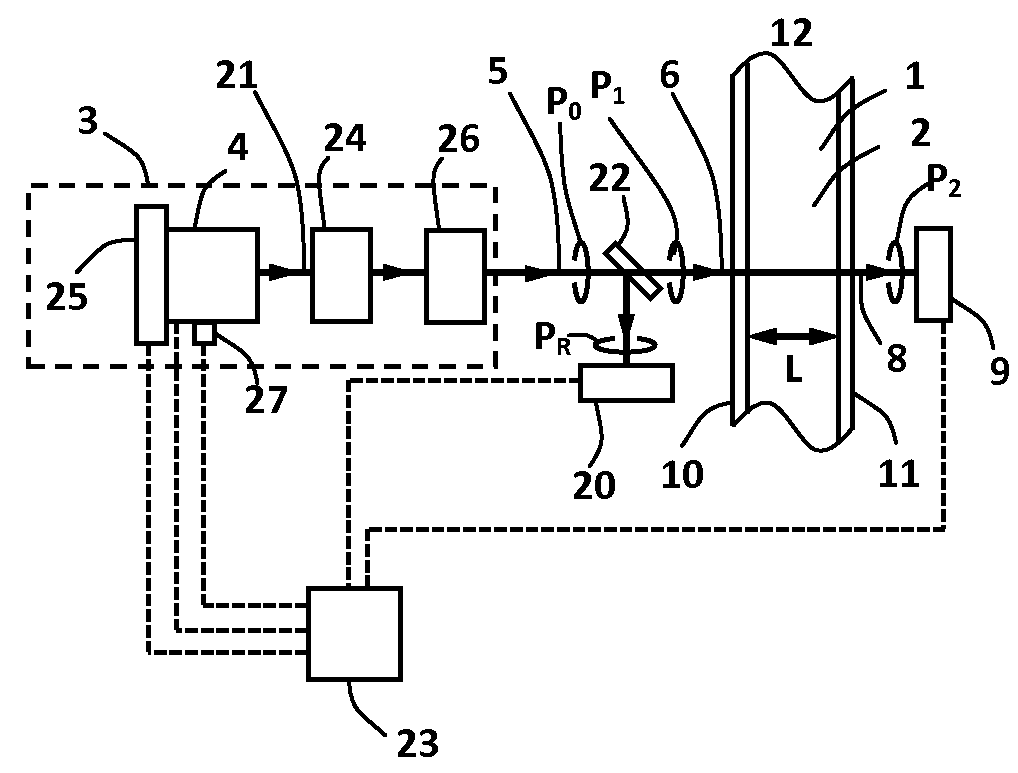
[0163]A schematic diagram of the sensor device is shown in FIG. 2. The sensor device includes a light source 3 including a solid-state light emitter 4, which emits light 21, an analyte 2 and analyte-handling means 12 (also referred to as a sample handling portion) including a first window 10 and a second window 11. Some or all of the light 21 is emitted from the light source 3 as emitted light 5. Some or all of this emitted light 5 is incident on the first window 10 as incident light 6 and the light propagates through the first window, through the analyte 2, through the second window 11, and the transmitted light 8 is incident on a first photodetection means 9. The first and second windows are s...

Example

Example 2

[0175]A second example of the invention is similar to the first example except that the solid-state light emitter 4 includes a laser. Many features are the same as for the first example and these may not be described again. This second example is illustrated in FIG. 2.

[0176]The solid-state light emitter 4 may be an optically pumped laser including AlyGa1-yN materials (0≦y≦1) or a laser diode including AlyGa1-yN semiconductor materials (0≦y≦1). In the remainder of this second example the solid-state emitter 4 is a laser diode including AlyGa1-yN semiconductor material emitting light 21 with a central wavelength of approximately 225 nm.

[0177]A laser is a preferred choice for the solid-state light emitter 4 in the light source 3 because it emits light with a narrower spectral bandwidth, it provides light with a wavelength which may be stabilised against variation more effectively than an LED, it may provide light which is substantially linearly polarised and it provides light ...

Example

Example 3

[0182]A third example of this invention is now described. The third example is similar to the first and second examples and common features may not be repeated. In this third example, which is illustrated in FIG. 5, deep ultraviolet light in the wavelength range 200 nm-240 nm is generated by frequency-conversion of longer wavelength light emitted by a solid-state light emitter which is a semiconductor laser such as a laser diode.

[0183]The sensor device includes a light source 30 in which the solid-state light emitter 4 is a semiconductor laser which emits light 21 that passes through one or more frequency-converting elements 31. The semiconductor laser emits light with a central wavelength between a lower value of approximately 400 nm and an upper value or approximately 480 nm. In this example the semiconductor laser emits light 21 with a central wavelength of approximately 450 nm. The semiconductor laser in this example is a Fabry-Perot laser diode including AlyInxGa1-x-yN...


PUM


Abstract

A sensor for measuring a concentration of a particular ion, molecule or atom in a fluid includes a sample handling portion for providing at least some of the fluid, a first photo-detection device, and a first light source. The first photo-detection device is configured to measure a power of light incident thereon, and the first light source includes a solid-state light emitting device. The first light source is configured to emit light having a wavelength less than 240 nanometers incident on the fluid provided by the sample handling portion, and the first photo-detection device is configured to receive light having passed through the fluid.

Description

TECHNICAL FIELD[0001]This invention relates to optical sensors using solid-state light sources for fluid analysis applications.BACKGROUND ART[0002]It is important to be able to measure the concentration of species such as molecules or ions in a fluid in a range of technical fields, including for environmental, health and industrial applications. There is, therefore, a strong demand for reliable, low-cost and long lifetime sensor technologies which can be used to measure the concentration of species such as chemical molecules and ions in fluids.[0003]For example, there is a significant demand for sensors to measure the concentration of the nitrate ion (NO3−) in drinking water and waste water. The nitrate ion is suspected of being harmful to humans and animals and there are limits placed on the concentration of nitrate ions found in potable water, such as 10 mg / litre nitrate ion as nitrogen (NO3−—N) concentration in the United States and 50 mg / litre nitrate ion (NO3−) concentration in...

Claims


Application Information

Patent Timeline
IPC IPC(8): G01N33/18G01N21/53G01N21/59G01N21/85
CPCG01N33/188G01N21/532G01N21/59G01N21/85G01N21/3103G01N21/33G01N2021/3188
Inventor SMEETON, TIM MICHAELBOARDMAN, EDWARD ANDREWMORI, JUN
Owner SHARP KK
Why Eureka
Try Eureka