Eureka AIR delivers breakthrough ideas for toughest innovation challenges, trusted by R&D personnel around the world.

White balance correction apparatus and method

a technology of white balance correction and apparatus, which is applied in the field of apparatus and methods for correcting the white balance of an image signal, can solve the problems of low sensitivity digital camera that cannot capture a weak light amount from a light source other than the main light source, and affect the color balance of the skin color portion of the face, etc., and achieves the effect of well color-balanced

Active Publication Date: 2008-09-04
FUJIFILM CORP
View PDF4 Cites 49 Cited by
  • Summary
  • Abstract
  • Description
  • Claims
  • Application Information

AI Technical Summary

Benefits of technology

[0014]wherein, if the first and second white balance correction values are different from each other, white balance in the region other than the specific target is corrected using the first white balance correction value and white balance in the specific target region is corrected using the second white balance correction value. That is, for the region detected as a specific target, white balance is corrected by the second white balance correction means, and for the other region, white balance is corrected by the first white balance correction means. This allows a white balance correction of a subject according to the light source, so that photographing of a natural image is possible even under a plurality of light sources.
[0020]In the white balance correction apparatuses described above, a human face is generally conceivable as a particular example of the specific target. That is, if the specific target is a face, it is possible to perform a white balance correction on the face portion which does not give uncomfortable feeling by applying the white balance correction described above.
[0032]According to the present invention, the region of a specific target included in inputted image signals is regarded as a main subject, and a main light source white balance correction value for the main light source that illuminates the main subject and a subsidiary light source white balance correction value for the subsidiary light source that illuminates the region other than the specific target in the image are obtained. If the main light source white balance correction value and the subsidiary light source white balance correction value are different from each other, it is determined that the main light source and the subsidiary light source are different, and an optimum white balance correction is performed on each of the regions. This allows a well color-balanced image as a whole to be obtained even for a subject illuminated by a plurality of types of light sources by optimally controlling the white balance correction values.
[0033]Further, even when a main subject is illuminated by a plurality of light sources, white balance correction values may be controlled optimally and a well color-balanced image as a whole may be obtained by dividing the main subject region including the specific target into a plurality of segments, obtaining a segment white balance correction value for each of the segments and performing a correction thereon.

Problems solved by technology

Consequently, this might cause, for example, disruption of color balance between the skin color portion of a face and the portion other than the skin color portion, such as the eyes or the like.
The reason is that the low sensitivity digital camera is unable to capture a weak light amount from a light source other than the main light source.
Further, when the subsidiary light source is an incandescent color fluorescent lamp or the like, a similar problem still arises.

Method used


Image

  • White balance correction apparatus and method
  • White balance correction apparatus and method
  • White balance correction apparatus and method

Examples


first embodiment

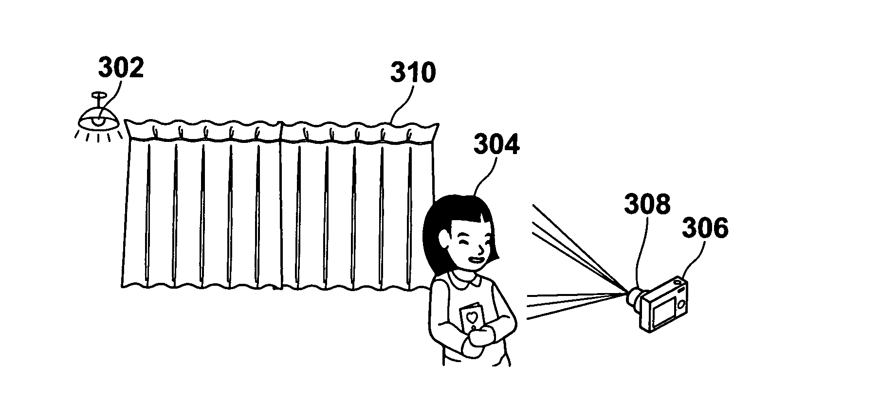
[0066]Hereinafter, a first embodiment will be described. FIG. 3 illustrates a first example subject illuminated by a plurality of light sources. The white balance correction for the picture signals obtained under such circumstances will be described as an example. The example subject is an indoor room illuminated by a ceiling light 302 of incandescent lamp. When photographing a person, which is a main subject 304, a built-in flash or an accessory flash to a photographing device 306 is sometimes used. Here, a background curtain 310 and the like are illuminated by the ceiling light 302, and the main subject 304 is illuminated by the flash 308, thus creating an area within the subject illuminated by a plurality of light sources.

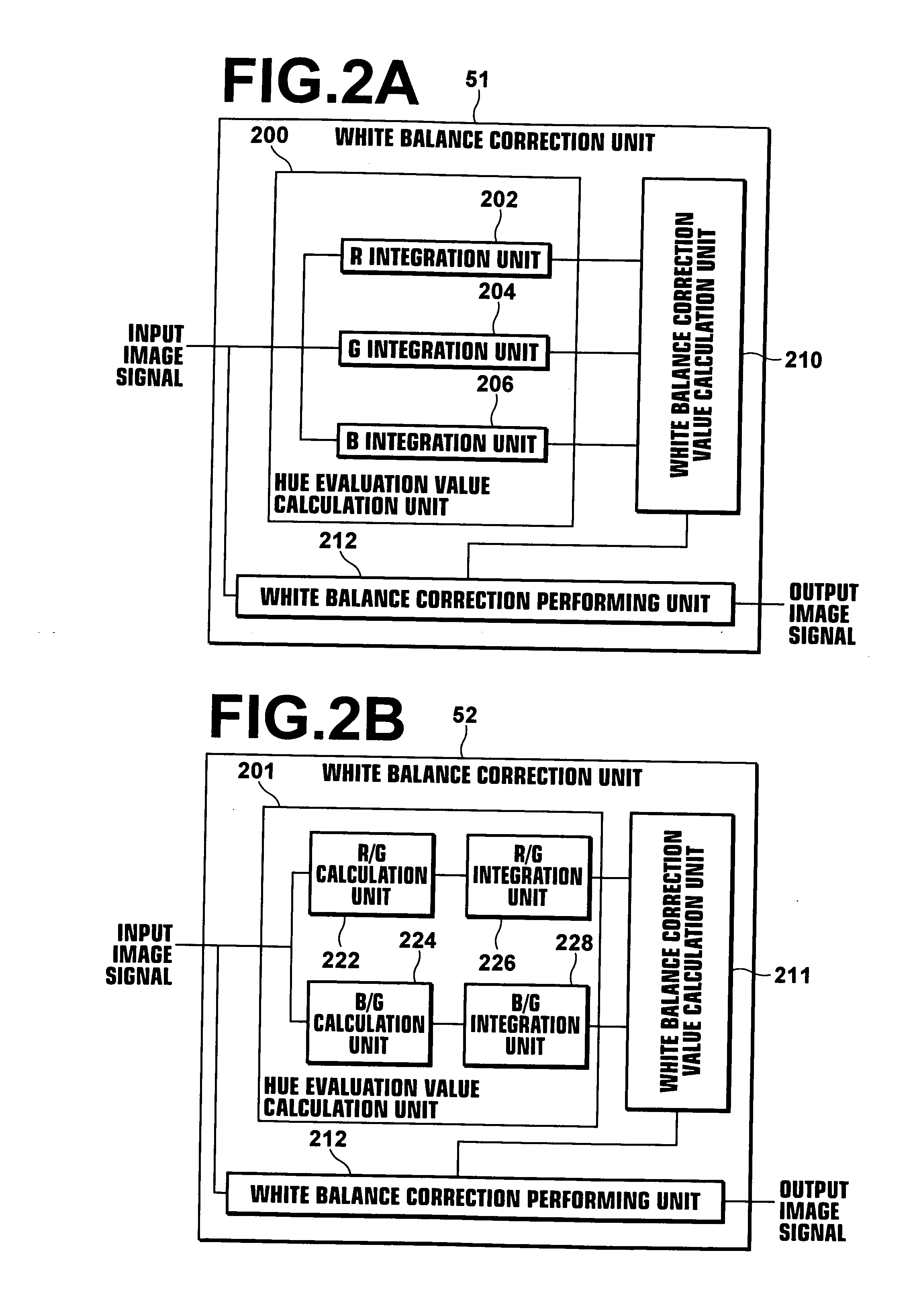
[0067]FIG. 4A illustrates a photograph image of the first example subject illuminated by a plurality of light sources shown in FIG. 3, and FIG. 4B illustrates an specific target region 406 detected from FIG. 4A. FIG. 5A illustrates an example configuration of th...

second embodiment

[0083]In the first embodiment, the white balance correction unit 50 is formed by hardware. But it may be embodied by software operating on the CPU 20. This is shown in FIG. 6 and Figures following thereto, and will be described as a second embodiment.

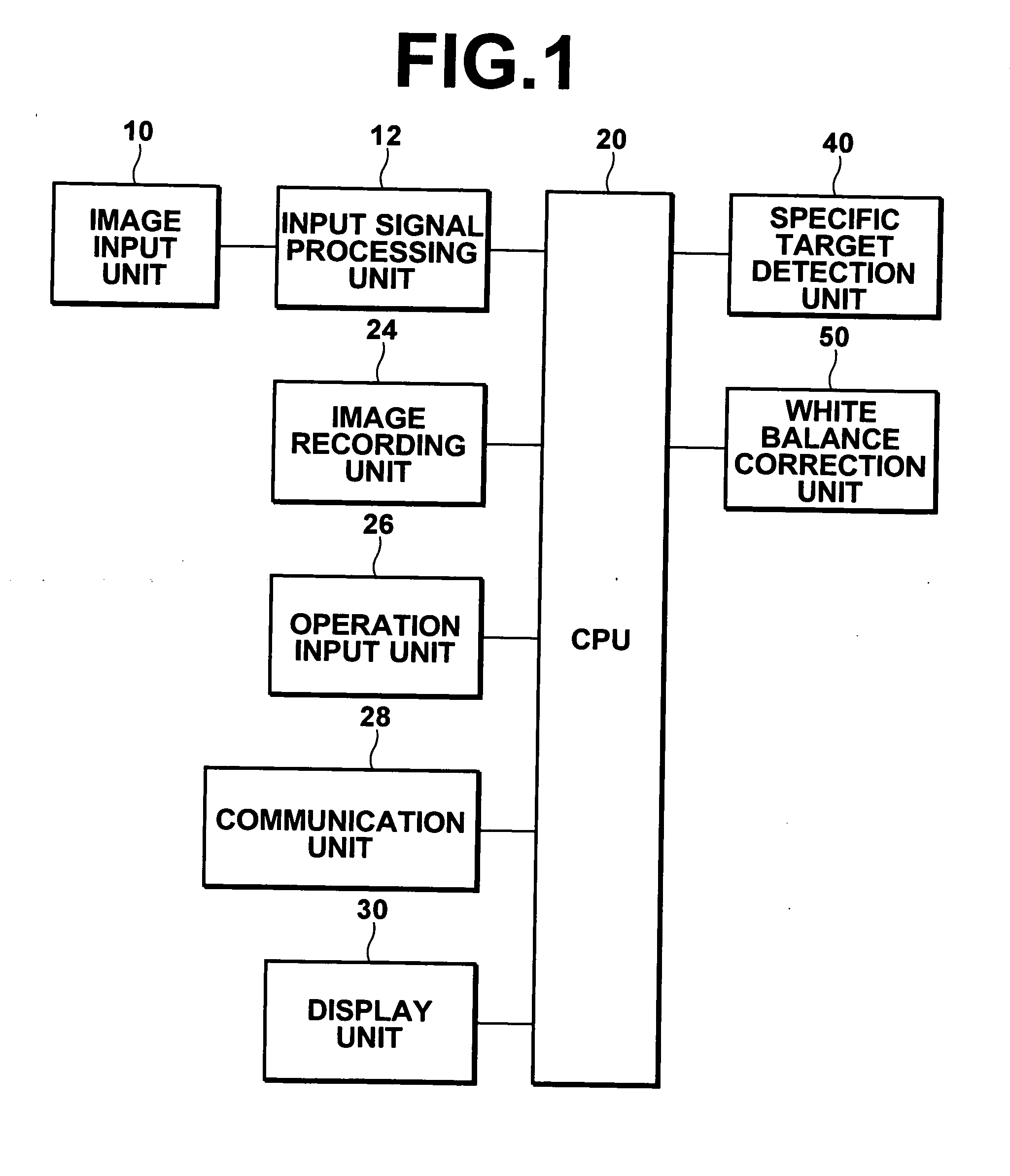
[0084]FIG. 6 is a block diagram of an imaging apparatus 2 as an embodiment of the white balance correction means according to the present invention, illustrating the internal configuration thereof. The imaging apparatus 2 shown in FIG. 6 does not include the white balance correction unit 50 shown in FIG. 1, but the identical function is realized by the software operating on the CPU 20. The other portion is identical to that shown in FIG. 1, and it will not be elaborated upon further here.

[0085]FIG. 7 is a flowchart as an embodiment of the white balance correction value calculation means according to the present embodiment. Here, due to software processing, image signals are divided into K blocks in the x direction, and L blocks in the y...

example modification

of the Second Embodiment

[0098]In the second embodiment, the use of the first or second white balance correction value is determined with respect to each block (step S806 in FIG. 8). It is possible, however, that an intermediate region between the specific target region and the region other than the specific target region may exist. If such is the case, the use of a white balance correction value according to the intermediate region allows a more effective white balance correction. This will be described as an example modification of the second embodiment.

[0099]FIGS. 9A to 9C illustrate an example case in which a low-pass filter is applied to the block discrimination value B(X, Y). As described earlier, the block discrimination value B(X, Y) is set to “1” if the block is the first hue evaluation value calculation region, or set to “2” if the block is the second hue evaluation value calculation region. The first or second white balance correction value is applied according to the firs...


PUM


Abstract

A specific target included in an image is detected by a specific target detection unit based on a specific target evaluation value representing likeliness of the specific target. Using a first white balance correction value calculation unit for obtaining a first white balance correction value for the region of the image other than the specific target, a second white balance correction value calculation unit for obtaining a second white balance correction value for the specific target region, and a white balance correction value comparison unit for making a comparison between the first and second white balance correction values, white balance in the region other than the specific target is corrected using the first white balance correction value, and white balance in the specific target region is corrected using the second white balance correction value, if the white balance correction values are different from each other.

Description

BACKGROUND OF THE INVENTION[0001]1. Field of the Invention[0002]The present invention relates to an apparatus and method for correcting the white balance of an image signal.[0003]2. Description of the Related Art[0004]In photographing devices, such as digital cameras and the like, it is well known that white balance corrections are performed on subject images after they are converted to image signals by the photographing device.[0005]Japanese Unexamined Patent Publication No. 6(1994)-121332 discloses a picture signal processing system that detects a skin color region or a human face from picture signals and performs luminance correction, color correction, and aperture correction only on the detected region. That is, it discloses a technique for improving skin color reproducibility by regarding a skin color region in picture signals as a face region and performing a color correction on the face region. According to the disclosed technique, the improvement of skin color reproducibilit...

Claims


Application Information

Patent Timeline
Patent Type & Authority Applications(United States)
IPC IPC(8): H04N9/73
CPCH04N9/735H04N23/88H04N9/73H04N23/70
Inventor MISAWA, TAKESHIOISHI, MAKOTO
Owner FUJIFILM CORP
Why Eureka
Eureka Blog
Learn More