
Pole alarm system

a technology of alarm system and telescopic mast, which is applied in the direction of alarms, load-engaging elements, instruments, etc., can solve the problems of extreme risk to the life and equipment of maintenance workers, extensive damage to equipment, and injury or death of personnel

Inactive Publication Date: 2001-06-26
WILL BURT CO
View PDF10 Cites 19 Cited by
  • Summary
  • Abstract
  • Description
  • Claims
  • Application Information

AI Technical Summary

Benefits of technology

Another object of the present invention is to provide a Pole Alarm System including a light source to illuminate the area of intended movement of the mast to enhance the operator's ability to safely control the equipment.
Another object of the present invention is to provide a Pole Alarm System capable of providing both audible and control feedback to alert the operator of impending contact and to automatically stop movement of the mast into a hazardous zone.

Problems solved by technology

Similarly, utility crews must elevate maintenance workers to reach and repair damage to power and telephone lines often during inclement weather and at night.
Although few problems are encountered while raising such a mast in open areas having good visibility, the maintenance workers' life and equipment is subject to an extreme risk when overhead electrical transmission lines and / or physical obstructions are encountered particularly at night or during other poor visibility conditions.
In a number of instances contact with electrical wires and collisions with overhead obstructions have resulted in the injury or death of personnel and extensive damage to equipment.

Method used


Image

  • Pole alarm system
  • Pole alarm system
  • Pole alarm system

Examples


Embodiment Construction

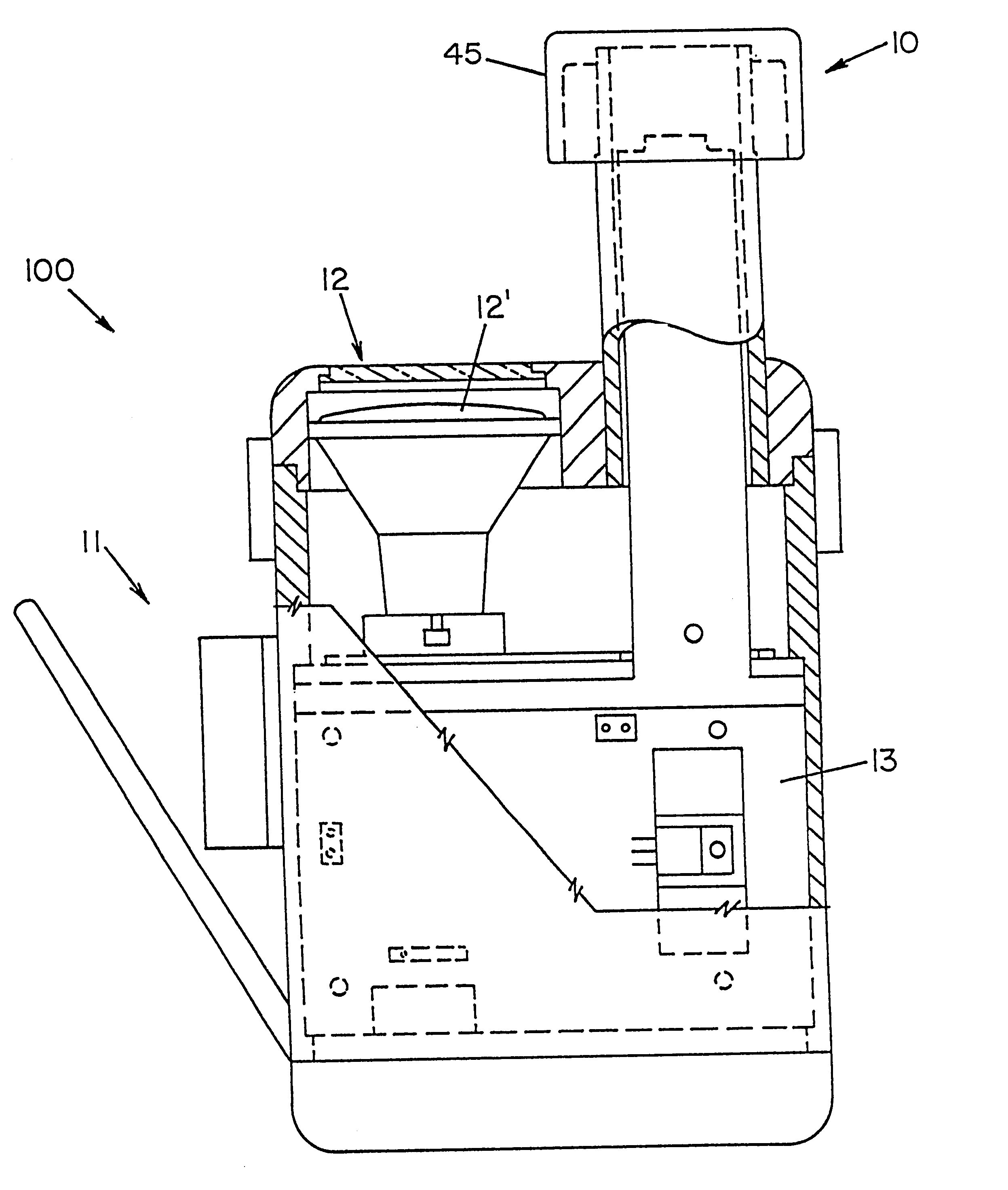
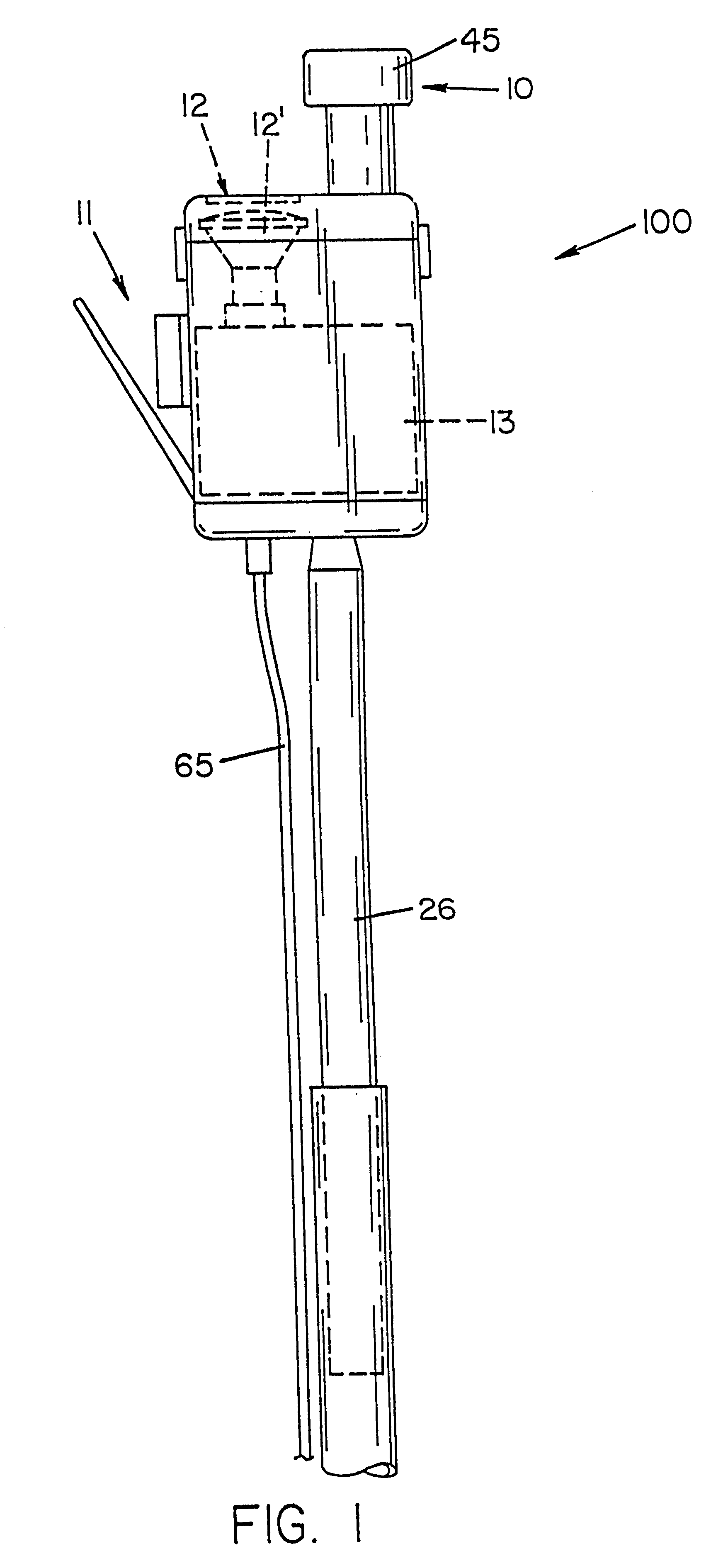
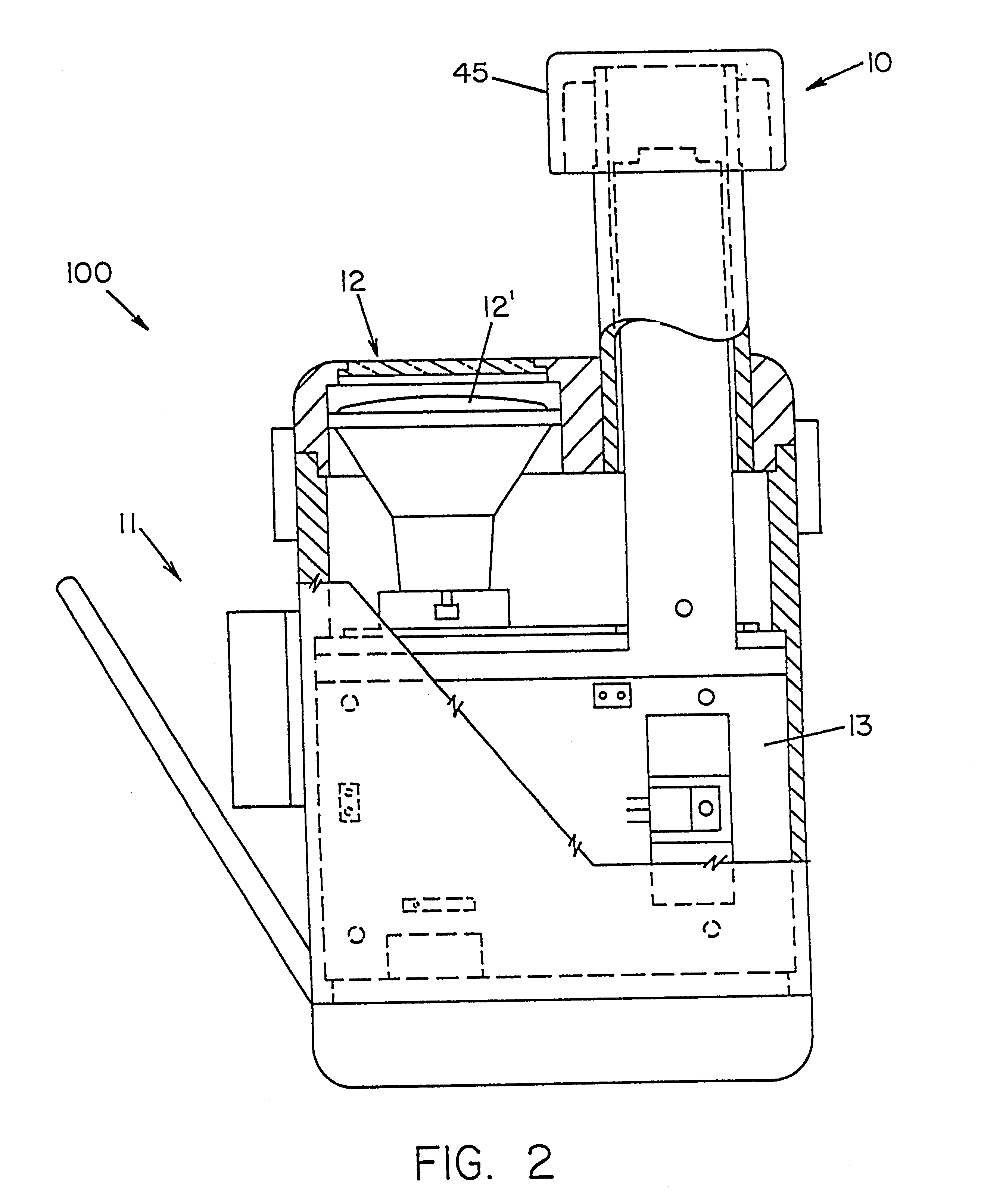
With further reference to the drawings there is shown therein a view of the pole alarm housing, indicated generally at 100, disposed on a telescoping mast 25 of the type used on a boom truck. There is shown in FIG. 2 an enlarged view of the pole alarm housing 100 and the components contained therein including the AC (alternating current) detector antenna, indicated generally at 10, the Collision detector unit, indicated generally at 11, a light source or so-called Lookup Light, indicated generally at 12 and the integrated control unit, indicated generally at 13.

It will be understood that the housing 100 must be disposed at the highest point of the telescoping mast 25 as shown in FIG. 1 and directed generally upwardly in its functional position. There must be no obstructions to either the AC detector 10 or the collision detector 11 for the present alarm system to function properly.

The AC detector antenna 45 protrudes above the housing 100. The halogen spotlight bulb 12' of the Lookup...


PUM


Abstract

A Pole Alarm System including an electromagnetic field sensor and collision sensors for detecting overhead power lines and physical obstructions within the intended path of a telescoping mast or utility boom device is disclosed. The present alarm system includes a mast-mounted housing containing the sensors and a microprocessor-based control unit which interprets the output signals of the sensors and provides both audible and control feedback to a safety control module in the vehicle to alert the operator of impending contact and to automatically stop the movement of the mast. The alarm housing also features a light source which provides illumination in the direction of movement of the mast to assist in positioning thereof. The light source also functions as a heating element to prevent the accumulation of ice on the housing which would detrimentally affect the performance of the system. The alarm housing also includes a plurality of Tilt sensors which monitor the orientation of the mast to prevent mast extension if the device deviates from an acceptable range of operation. A system integrated safety control module mounted in the vehicle provides self-test functions and an error code display to alert the operator to the cause of an alarm signal.

Description

BACKGROUND OF INVENTIONThe present invention relates generally to alarm systems and, more particularly, to a collision avoidance alarm for a telescoping mast.Telescoping masts of the type including a plurality of extensible, interconnected sections operated by pneumatic, hydraulic, or mechanical power are well known to those skilled in the art. For example, such telescoping masts are used extensively in the broadcast industry to elevate antennas for remote transmission of audio and video signals. Such a telescoping mast is also utilized on utility repair trucks having elongated boom including a so called "cherry picker" that is used by public and private utility maintenance crews to reach elevated power, cable, and telephone transmission lines. Similarly, the present Pole Alarm system is also suitable for use on ladder trucks, cranes, hoists, and other related equipment.Remote broadcast antennas mounted on telescoping masts or poles must often be rapidly deployed under severe weathe...

Claims


Application Information

Patent Timeline
IPC IPC(8): B66C15/00B66C15/06
CPCB66C15/065
Inventor BECKMANN, UWE L.
Owner WILL BURT CO
Learn More