Oxygen battery system

a battery system and oxygen battery technology, applied in the field of oxygen battery systems, can solve the problems of high current generation, possible fire, and severe safety problems of batteries using metallic lithium anodes

Inactive Publication Date: 2009-09-24
JOHNSON IP HLDG LLC
View PDF66 Cites 52 Cited by
  • Summary
  • Abstract
  • Description
  • Claims
  • Application Information

AI Technical Summary

Problems solved by technology

Batteries using metallic lithium anodes have posed severe safety issues due to the combination of a highly volatile, combustible electrolyte and the active nature of the lithium metal.
Internal failures resulting in self discharge can produce a high current generation, overheating and ultimately, a possible fire.
The main problem associated with metallic lithium anodes has been mossy lithium growth during recharge.
Low density lithium plating during the recharging process can grow through the separator / electrolyte resulting in an internal short circuit.
These cells can degenerate to the point where high temperature levels in combination with volatile electrolyte and mossy lithium participates in a burning reaction releasing high levels of energy and a violent rupture of the battery casing or containment vessel.
Although these batteries are much safer than earlier designs, violent failures may still occur.
The problem is that conventional lithium ion batteries contain all of the chemical reactants necessary to produce the reaction energy potential of the cell.
An internal failure can cause these materials to react with each other and violently release their stored energy as heat.
Access of internal reactants to each other in the event of an internal failure cannot be controlled in lithium ion (Li-Ion) cells.

Method used


Image

  • Oxygen battery system
  • Oxygen battery system
  • Oxygen battery system

Examples


Embodiment Construction

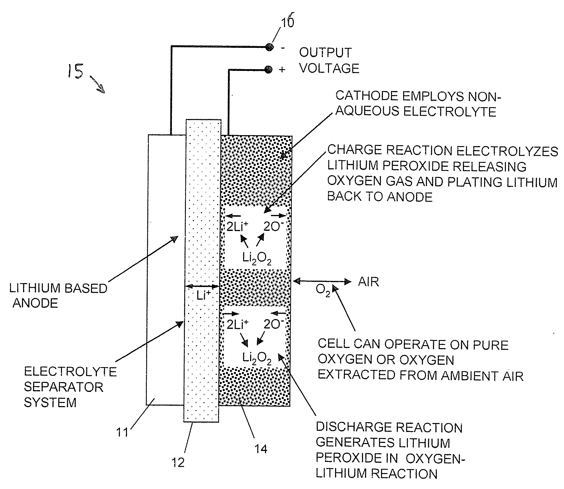
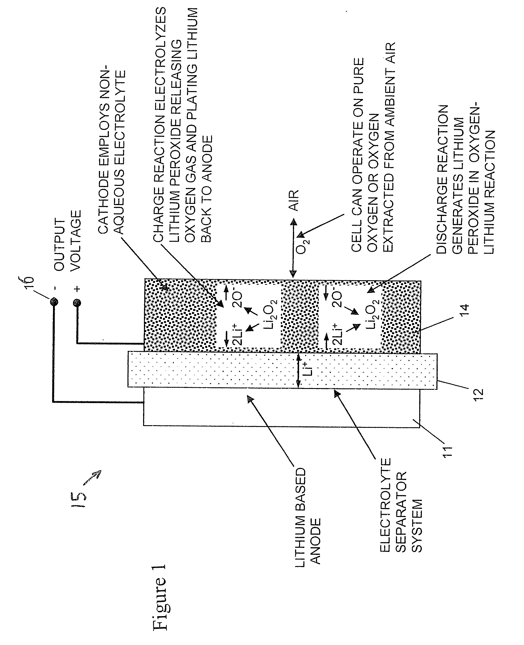
[0013]With reference next to the drawings, there is shown a lithium oxygen cell system 10 in a preferred form of the invention. The lithium oxygen cell system 10 includes a lithium oxygen electrochemical cell, lithium oxygen battery cell or lithium air cell 15 (these terms used interchangeably herein) constructed using carbon (carbon black based cathodes (with or without an added oxygen dissociation-promoting catalyst such as manganese dioxide) dispersed within a polymeric binder material and incorporating a metal screen as the conductive element. Maximum specific energy storage capacity is achieved with the use of lithium metal as an anode; however, graphite lithium intercalation anodes can be used to form lithium ion air cells using an appropriate separator design.

[0014]As best shown in FIG. 1, the lithium air cell 15 includes a lithium anode 11, an electrolyte separator 12, an air cathode 14 and battery terminals 16. Lithium-air cells or batteries produce electricity by electroch...


PUM

PropertyMeasurementUnit
volatileaaaaaaaaaa
chemical reaction potentialaaaaaaaaaa
metallicaaaaaaaaaa

Abstract

A lithium oxygen cell system (10) includes a battery cell (15), a containment vessel (106) having an air inlet conduit (114) and an air outlet conduit (112). An access control valve (101), a one way check valve (102), a H2O scrubber (103) and a CO2 scrubber (104) are mounted within inlet conduit. A one way check valve (107) and a forced air device (108) are mounted within outlet conduit. A charge controller (109) is coupled to battery and to the air device. The pair of one way check valves insure that the inside of the containment vessel (106) may be sealed. The system further includes a safety controller (111) coupled to an environmental sensor (110), and to control valve (101). When an unsafe temperature or pressure condition is detected, it closes control valve to shut down operation of the battery and thereby prevent a catastrophic event.

Description

REFERENCE TO RELATED APPLICATION[0001]Applicant claims the benefit of U.S. Provisional Patent Application Ser. No. 61 / 038,173 filed Mar. 20, 2008.TECHNICAL FIELD[0002]This invention relates to oxygen batteries, and specifically to oxygen battery systems having safety features.BACKGROUND OF THE INVENTION[0003]Batteries using metallic lithium anodes have posed severe safety issues due to the combination of a highly volatile, combustible electrolyte and the active nature of the lithium metal. These batteries store energy as a chemical reaction potential between internally contained materials. Internal failures resulting in self discharge can produce a high current generation, overheating and ultimately, a possible fire.[0004]The main problem associated with metallic lithium anodes has been mossy lithium growth during recharge. Low density lithium plating during the recharging process can grow through the separator / electrolyte resulting in an internal short circuit. The heat generated b...

Claims


Application Information

Patent Timeline
Patent Type & Authority Applications(United States)
IPC IPC(8): H01M2/00
CPCH01M2/1094H01M8/04156Y02E60/50H01M10/4235H01M12/08H01M8/0668H01M50/24Y02E60/10
Inventor JOHNSON, LONNIE G.
Owner JOHNSON IP HLDG LLC
Why Eureka
Try Eureka