Vehicle-mounted safety control apparatus

a safety control and vehicle technology, applied in pedestrian/occupant safety arrangements, braking systems, instruments, etc., can solve the problems of superfluous collision risk with a following, forward obstacle cannot be detected by the monitoring sensor, etc., and achieve the effect of accurate collision determination and likelihood of collision

Inactive Publication Date: 2010-01-28
DENSO CORP
View PDF14 Cites 52 Cited by
  • Summary
  • Abstract
  • Description
  • Claims
  • Application Information

AI Technical Summary

Benefits of technology

[0015]According to the above vehicle-mounted safety control apparatus, it is possible to terminate the automatic brake operation once activated if the likelihood of collision with an obstacle ahead of the vehicle is relatively low, to thereby prevent collision with an obstacle behind the vehicle such as the following vehicle.
[0017]According to the above configuration, it is possible to smoothly change the vehicle from the automatic brake operation mode to the driver's operation mode when the vehicle speed becomes constant, if collision with an obstacle can be avoided.
[0019]According to the above configuration, it is possible to terminate the automatic brake operation once activated at an earlier timing as the likelihood of collision with an obstacle ahead of the vehicle becomes low, even if it is not possible to determine whether the vehicle has collided with the obstacle.
[0021]According to the above configuration, it is possible to determine that the likelihood of collision with an obstacle ahead of the vehicle is lower when the lateral offset is large, which enables making an accurate collision determination.

Problems solved by technology

This configuration causes the following problem when the forward obstacle cannot be detected by the monitoring sensor.
The situation where the forward obstacle cannot be detected by the monitoring sensor may occur when the forward obstacle has moved away from the vehicle, or when the vehicle is too close to the forward obstacle to detect the forward obstacle.
In the former case, there may arise superfluous risk of collision with a following vehicle by the own vehicle making an unnecessary sudden stop.

Method used


Image

  • Vehicle-mounted safety control apparatus
  • Vehicle-mounted safety control apparatus
  • Vehicle-mounted safety control apparatus

Examples


Embodiment Construction

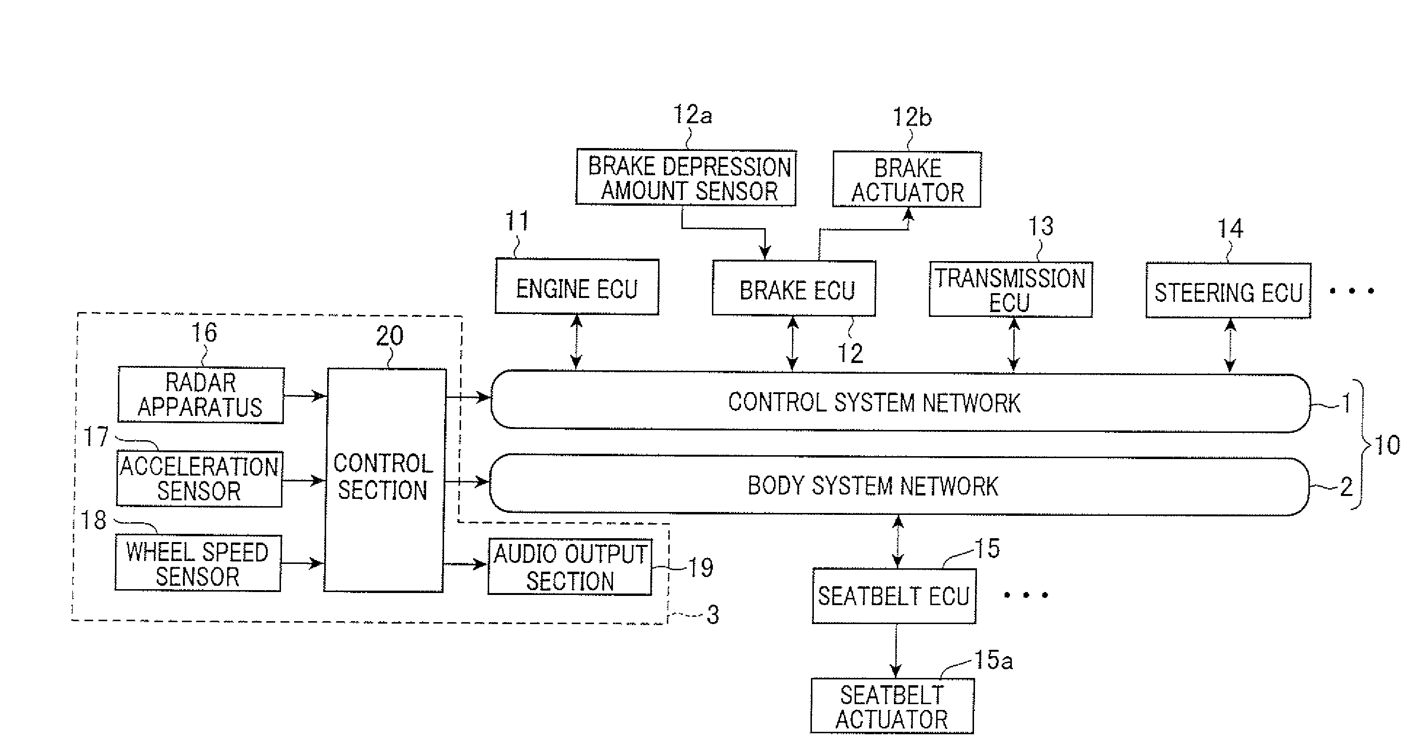
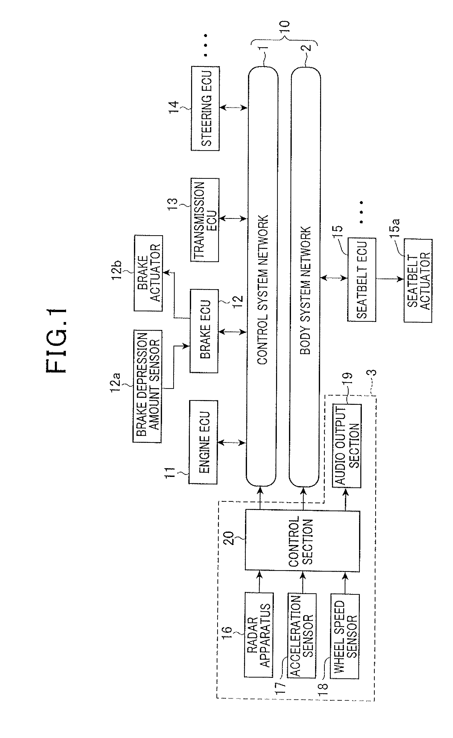
[0028]FIG. 1 is a block diagram showing a structure of an in-vehicle LAN connected with a vehicle-mounted safety control apparatus 3 according to an embodiment of the invention.

[0029]As shown in FIG. 1, the in-vehicle LAN is constituted of a control system network 1 connected with control system ECUs which operate to perform running control of the vehicle, and a body system network 2 connected with body system ECUs which operate to perform vehicle body control and provide various information. The vehicle-mounted safety control apparatus 3 is connected to both the network 1 and network 2.

[0030]The control system ECUs include an engine ECU 11 which controls start / stop of an engine (not shown) of the vehicle, fuel injection amounts and fuel injection timings, a brake ECU 12 which controls braking of the vehicle, a transmission ECU 13 which controls an automatic transmission of the vehicle, and a steering ECU 14 which performs steering control of the vehicle. Each of the ECUs 11 to 13 i...


PUM


Abstract

The vehicle-mounted safety control apparatus includes a first function of detecting an object ahead of the vehicle, a second function of acquiring, as a time to collision, a ratio of a relative speed to a relative distance between the vehicle and the object, a third function of performing an automatic brake operation when the time to collision is smaller than or equal to a predetermined time, a fourth function of detecting acceleration of the vehicle, and a fifth function of acquiring, as a collision acceleration, acceleration detected within a period having a predetermined duration and straddling a time at which the time to collision becomes 0, and operating to continue the automatic brake operation if the collision acceleration is larger than or equal to a collision threshold preset to a value larger than acceleration produced by the automatic brake operation, and otherwise terminate the automatic brake operation.

Description

CROSS-REFERENCE TO RELATED APPLICATION[0001]This application is related to Japanese Patent Application No. 2008-193757 filed on Jul. 28, 2008, the contents of which are hereby incorporated by reference.BACKGROUND OF THE INVENTION[0002]1. Field of the Invention[0003]The present invention relates to a vehicle-mounted safety control apparatus which performs safety control to prevent collision or reduce damage from collision with another vehicle, an obstacle, or a pedestrian.[0004]2. Description of Related Art[0005]There is known a vehicle-mounted safety control apparatus configured to calculate, as monitoring data, the distance and relative speed of another vehicle or an obstacle or a pedestrian (collectively referred to as a “forward obstacle” hereinafter) detected by use of a monitoring sensor such as a radar or a camera with respect to the vehicle on which the vehicle-mounted safety control apparatus is mounted (may be referred to as “own vehicle” hereinafter), and the position of t...

Claims


Application Information

Patent Timeline
Patent Type & Authority Applications(United States)
IPC IPC(8): B60T7/12B60R21/00B60T8/72
CPCB60R21/0134B60R2021/01265B60T7/22B60W30/09B60W2520/105G08G1/16B60W2540/12B60W2550/306B60W2550/308B60W2720/106B60W2520/28G08G1/166B60W2554/4041B60W2554/801B60W2050/143
Inventor ITO, YOSUKE
Owner DENSO CORP
Why Eureka
Try Eureka