Switching Power Supply With Overvoltage Protection And Overvoltage Protection Method Thereof

a technology of overvoltage protection and power supply, which is applied in the direction of power conversion systems, dc source parallel operation, ac network circuit arrangements, etc., can solve the problems of module inability to achieve overvoltage disconnecting protection, increase of cost, and many devices in the power supply module have insufficient resistance to voltag

Active Publication Date: 2009-06-18
VERTIV CORP
View PDF7 Cites 51 Cited by
  • Summary
  • Abstract
  • Description
  • Claims
  • Application Information

AI Technical Summary

Benefits of technology

[0017]A second voltage threshold is set in advance in the monitoring device, such that the second electric control switch is controlled by the monitoring circuit to return to the ON state when it is detected that the voltage is lower than the threshold.
[0018]The time of turning on or turning off of the first and second electric control switches is set, at the time the input voltage being lower than the bus line voltage, such that there is no current when the relay turns on or cuts off.
[0019]The advantages of the aforesaid technical solutions lie in that when the input voltage is higher than the predetermined protection voltage, a first electric control switch is turned off, and the main power circuit of the switching power supply is shut off. At the moment, the only branch that can supply electric energy to the successive stages is the soft start resistor branch. Since the second electric control switch is positioned in this branch, or positioned in the DC bus line after rectification, the actuation and release of the second electric control switch is controlled to control the input power supply to intermittently charge the power supply module, such that the output voltage after the rectifying circuit inside the power supply is controlled in a certain range, e.g. the second electric control is turned on when the output voltage is lower than a certain value (the value may be zero), and is turned off when the output voltage is higher than a certain value. Thus, it is ensured that the bus line voltage inside the power supply is controlled within a safe range, to ensure the safety of the devices inside the power supply; and at the same time to ensure the safety of the inner devices of the switching power supply, such that the auxiliary power supply and the control circuit can work normally. In other words, the auxiliary power supply and overvoltage protection is maintained by an alternating mode.

Problems solved by technology

Therefore, in the situation of overvoltage, the voltage of the input power supply can not be too high, otherwise insufficient withstand voltage will result in damage.
However, there may be a very high input voltage, e. g. when the input phase voltage is connected to a line voltage by accident, the input voltage will be as high as 380 Vac, and the peak voltage will exceed 500 Vdc, and many devices in the power supply module have insufficient withstand voltage at the moment.
However, in the switching power supply of prior art, the module can not achieve a overvoltage disconnecting protection when the AC voltage of the module is too high, because the operation of the auxiliary power supply stops after being disconnected from the AC voltage, and there is no power supply for maintaining the disconnecting device.
However, there exist the following problems that: 1) an additional device is required, which may cause the increase of the cost; 2) the whole system can not work normally when the additional device malfunctions.
However, by doing so, the module can not return to a normal operation state after the input voltage returns to a normal state, thus can not meet the requirement.

Method used


Image

  • Switching Power Supply With Overvoltage Protection And Overvoltage Protection Method Thereof
  • Switching Power Supply With Overvoltage Protection And Overvoltage Protection Method Thereof
  • Switching Power Supply With Overvoltage Protection And Overvoltage Protection Method Thereof

Examples


embodiment 1

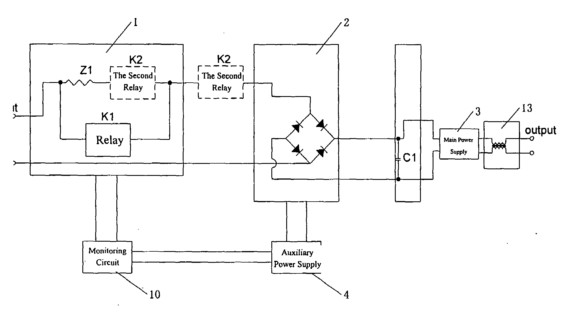
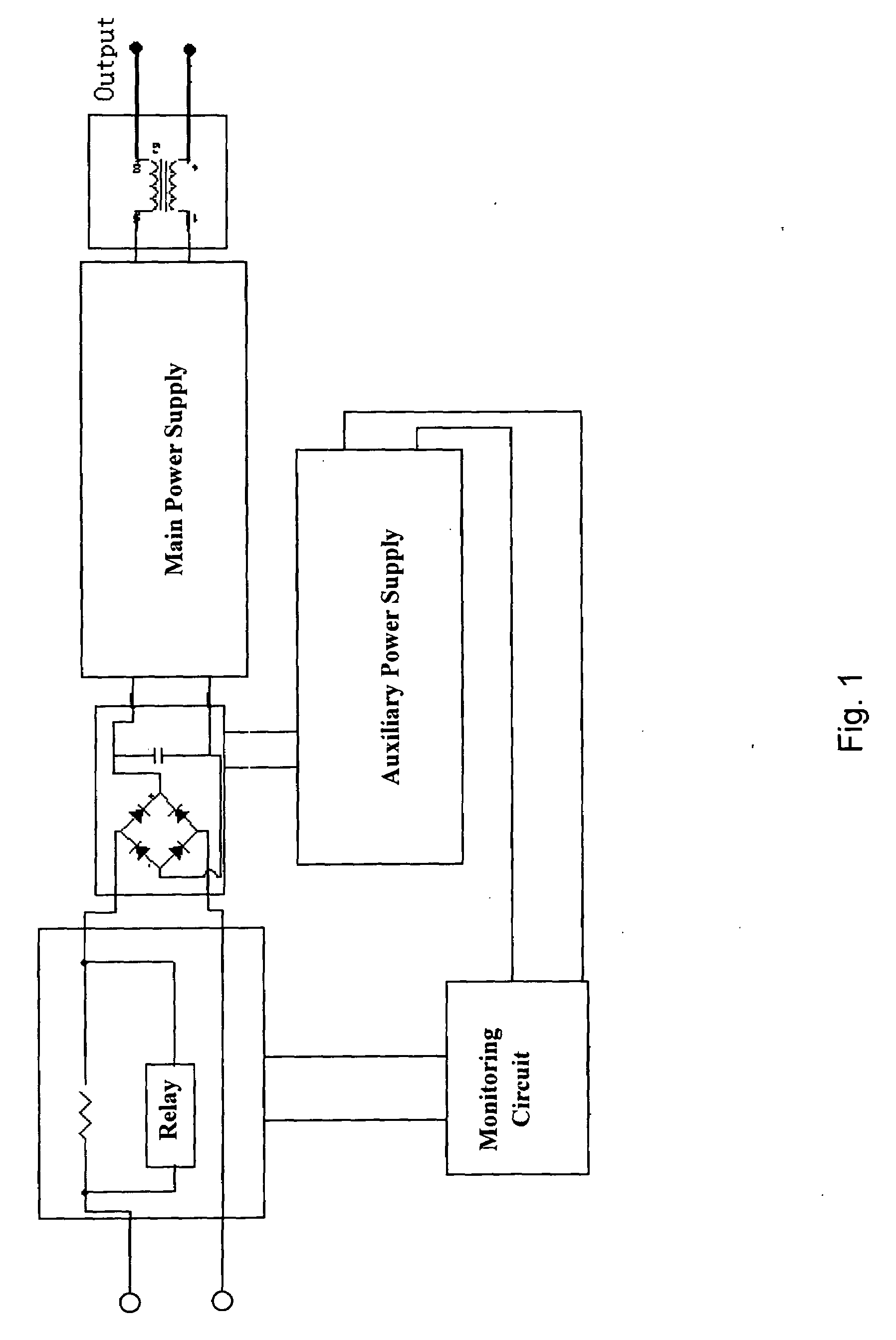
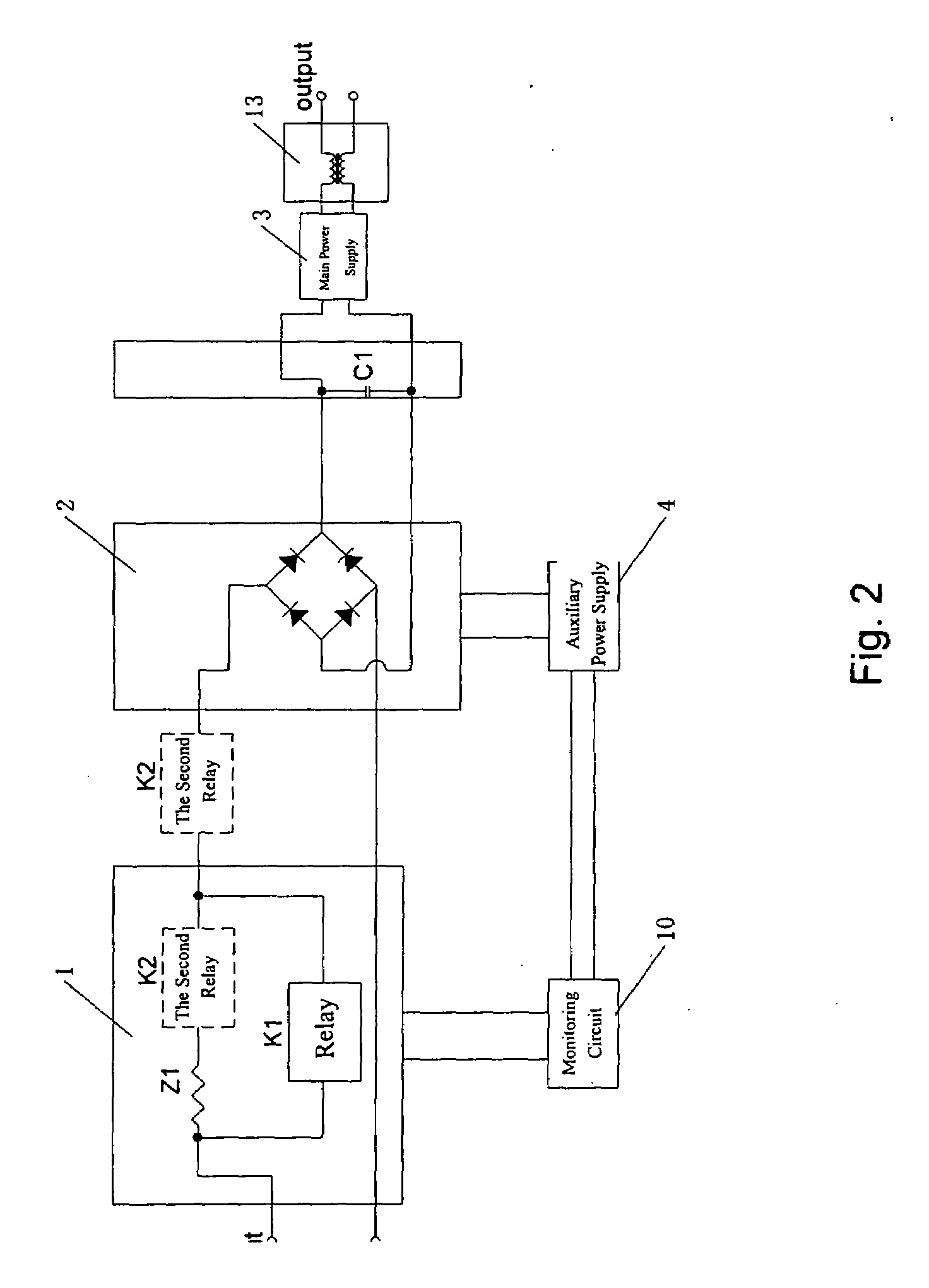
[0040]As shown in FIG. 3a, the first and second electric control switches K1, K2 are relays in the present embodiment, wherein the second relay K2 and the soft start resistor Z1 are connected in series, and then connected with the first relay K1 in parallel.

[0041]There are two kinds of control strategies as shown in the following depending on the step S4:

[0042]1) The first control strategy: The first electric control switch K1 is set to be in a normal open state, and the second electric control switch K2 is set to be in a normal close state in advance, such that when the energy stored in the filter capacitor C1 is consumed and is insufficient to actuate the second electric control switch K2, the second electric control switch K2 will be closed automatically, and return to an ON state.

[0043]2) The second control strategy: A voltage threshold is set in the monitoring device 10 in advance. When it is detected that the voltage is lower than the threshold, the second electric control swi...

embodiment 2

[0052]As shown in FIG. 4a, the present embodiment is characterized by an impedance Z2 connected in parallel with K2. It is preferable that a resistor is adopted as Z2. In FIG. 4a and figures thereafter, the monitoring circuit 10 is consisting of a logical decision circuit and a driving circuit.

[0053]The improved circuit has the same operating mode, and is characterized in that AC input continues to supply energy to the high voltage C1 through impedances Z1, Z2 when Z2 is in OFF state, such that the maintaining time of the auxiliary power supply, that is the duration of OFF state of K2 is elongated. Thus, the power consumption of Z1 is reduced significantly.

[0054]In the case that the resistance of Z2 becomes infinite, embodiment 2 is the same with embodiment 1.

embodiment 3

[0055]As shown in FIG. 4b, a third impedance Z3 connected in series with the second electric control switch K2 is provided compared with embodiment 2, and serially connected Z3 and K2 are connected in parallel with the second impedance Z2. This is because that Z3 is needed for avoiding an arc when Z2 is a capacitor.


PUM


Abstract

A switching power supply with overvoltage protection includes a soft start circuit, a rectifying circuit, a filter capacitor, a main supply, an auxiliary supply and a monitoring circuit. When the input voltage is higher than the predetermined protection voltage, a first electric control switch is turned off, and the main power circuit of the switching power supply is shut off. At the moment, the actuation and release of the second electric control switch is controlled so as to control the input power supply to intermittently charge the power supply module such that the output voltage downstream of the rectifying circuit inside the power supply is controlled in a safe range. For instance, the second electric control is turned on when the output voltage is lower than a certain value, and is turned off when the output voltage is higher than a certain value. Thus, it is ensured that the bus line voltage inside the power supply is controlled within a safe range, to ensure the safety of the devices inside the power supply; and at the same time to ensure the safety of the inner devices of the switching power supply, such that the auxiliary power supply and the control circuit can work normally.

Description

TECHNICAL FIELD[0001]The present invention relates to a switching power supply with overvoltage protection and overvoltage protection method thereof.DESCRIPTION OF THE RELATED ART[0002]In a switching power supply module, topology of circuit as shown in FIG. 1 is usually employed, comprising a soft start circuit, a rectifying circuit, a filter circuit (generally consisting of a filter capacitor), a main power supply (consisting of a main DC / DC converter and its output filter), an auxiliary power supply and a monitoring circuit. A power factor correction circuit, namely PFC circuit is provided between the rectifying circuit and the main power supply in some of the switching power supplies.[0003]If the voltage of the input power supply is too high, then some protective measures have to be employed for preventing damage to the power supply module. Common protective measure is to shut off the main circuit (PFC and the DC / DC converter) of the power supply, to stop the power output, and to...

Claims


Application Information

Patent Timeline
Patent Type & Authority Applications(United States)
IPC IPC(8): H02J3/00
CPCH02H7/1213H02M1/36H02M1/32H02H9/001
Inventor ZHANG, HUAJIANRU, YONGGANGYU, SHIQIANGCHEN, BAOGUO
Owner VERTIV CORP
Why Eureka
Try Eureka