Airbag apparatus

a technology of airbags and vent holes, which is applied in the direction of pedestrian/occupant safety arrangements, vehicular safety arrangements, vehicle components, etc., can solve the problems that the sized vent hole cannot discharge enough inflation gas, and the inflation gas may leak from the gap between the vent hole, etc., and achieve the effect of simple structur

Inactive Publication Date: 2009-10-13
TOYODA GOSEI CO LTD
View PDF8 Cites 34 Cited by
  • Summary
  • Abstract
  • Description
  • Claims
  • Application Information

AI Technical Summary

Benefits of technology

[0009]The present invention contemplates to solve the above-mentioned problems, and therefore, has an object to provide an airbag apparatus capable of controlling the opening and closing operations of the exhaust hole securely with a simple structure.

Problems solved by technology

However, if the patch element fails to securely seal the vent hole, inflation gas may leak from a gap between the vent hole and the patch element.
In order to secure a stable closed condition of the vent hole it is alternatively contemplated to reduce the size of the vent hole, but a small-sized vent hole cannot discharge enough inflation gas.

Method used


Image

  • Airbag apparatus
  • Airbag apparatus
  • Airbag apparatus

Examples


first embodiment

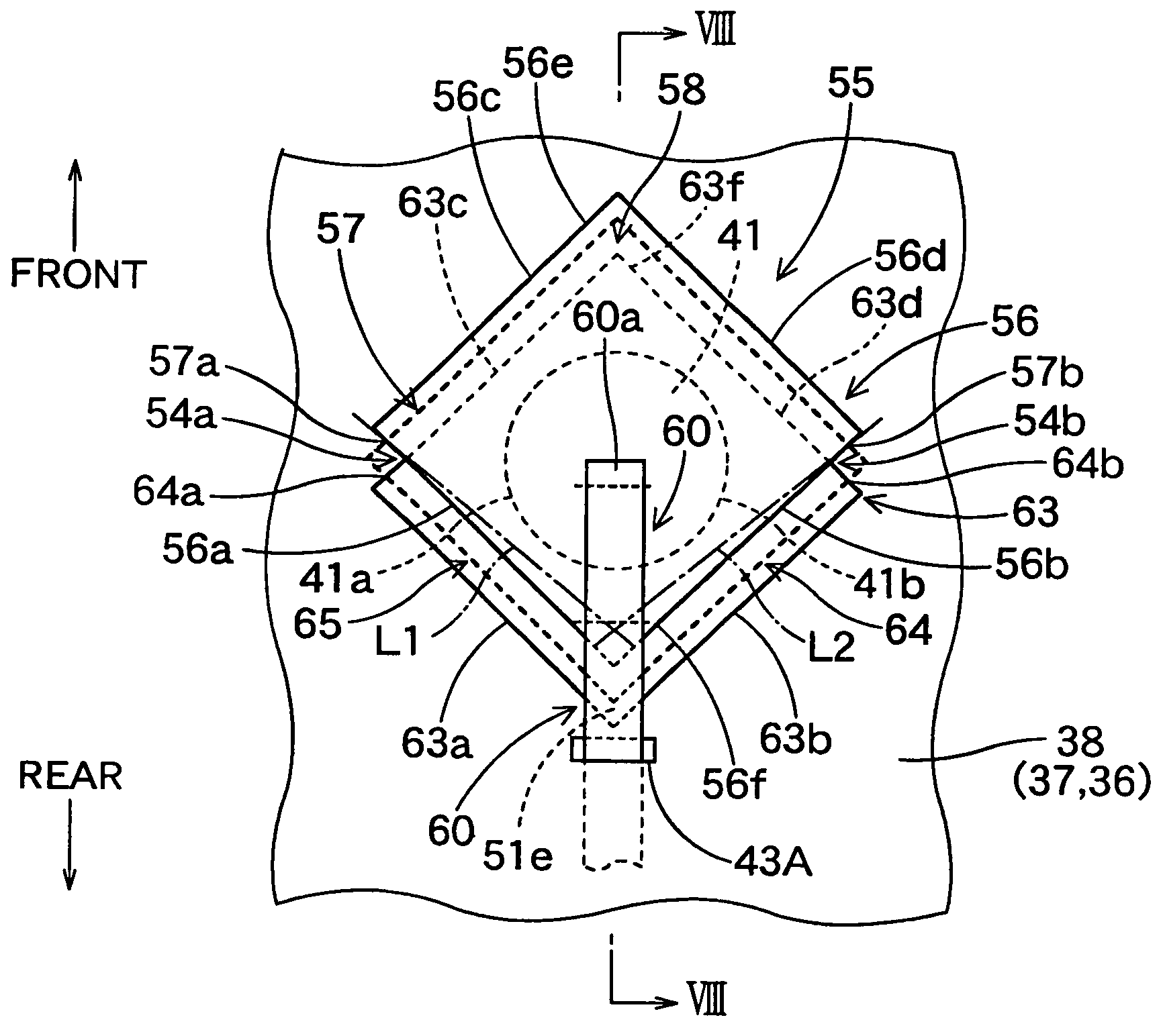
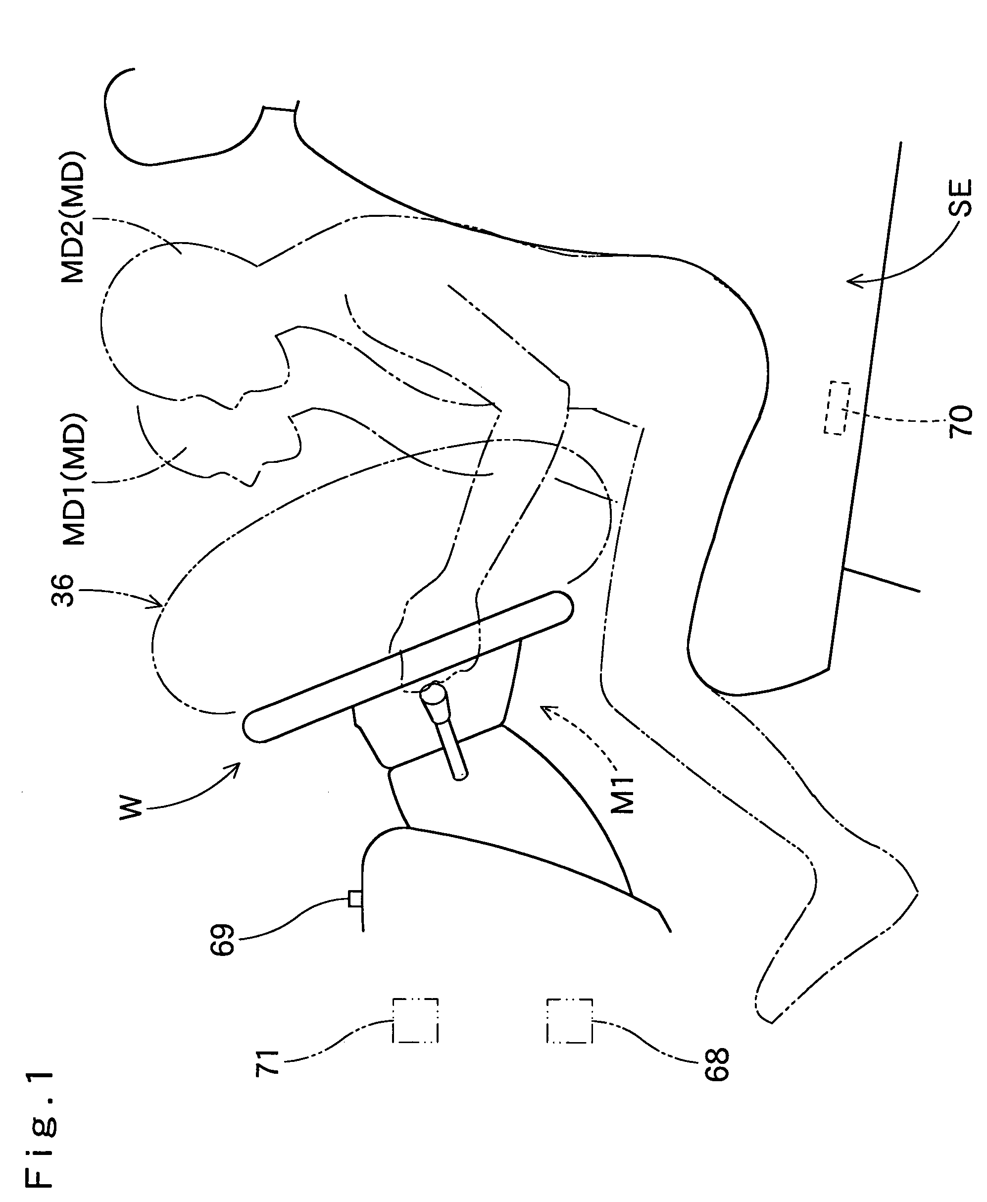
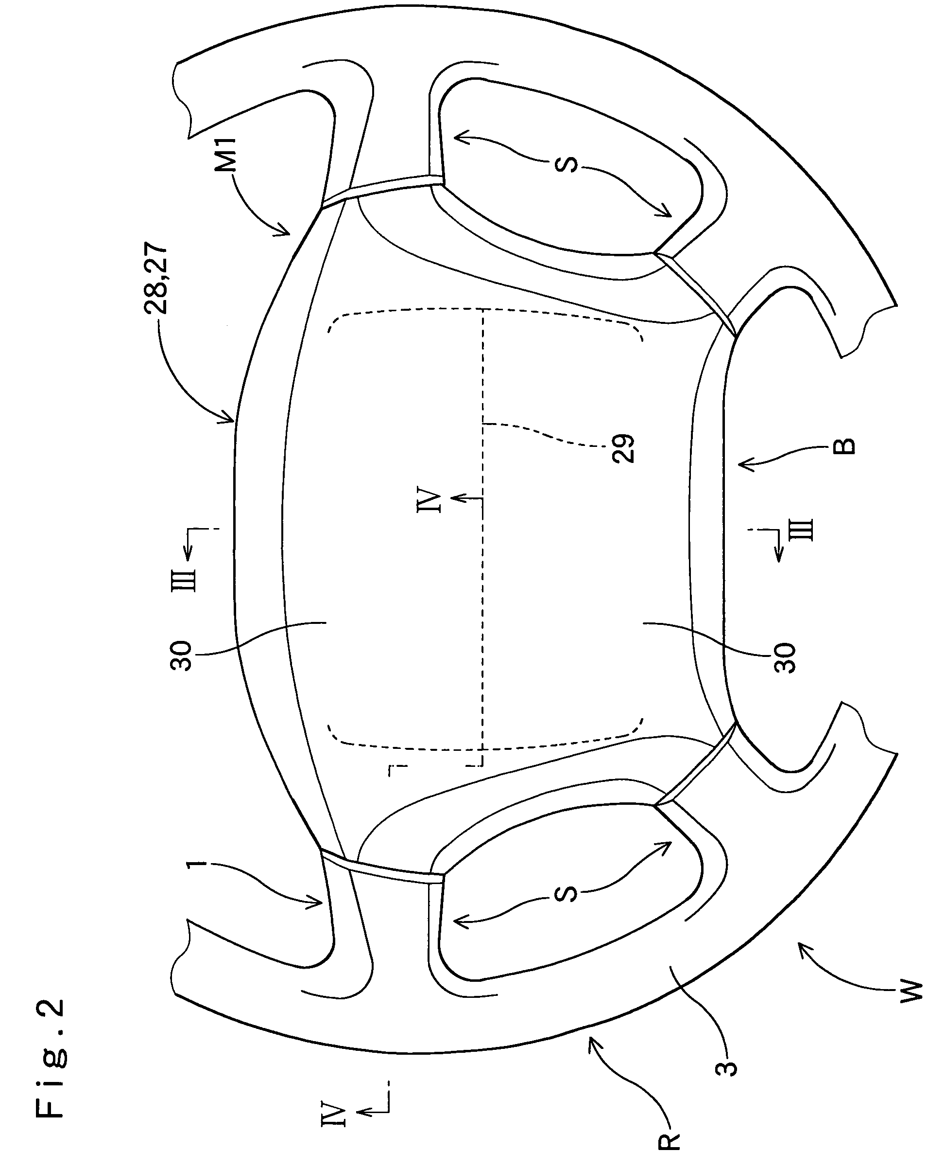
[0109]FIGS. 1 to 4 illustrate an airbag apparatus M1 for a steering wheel which is the present invention.

[0110]Unless otherwise specified, the front-rear, up-down, and left-right directions in this specification are based on a steering wheel W mounted on a vehicle being steered straight forward. Specifically, the up-down is defined by the up-down direction extending along the axial direction of a steering shaft SS (refer to phantom lines in FIGS. 3 and 4) on which the steering wheel W is to be mounted. The front-rear is defined by the vehicle's longitudinal direction running perpendicularly to the axial direction of the steering shaft SS, and the left-right is defined by the vehicle's lateral direction running perpendicular to the axial direction of the steering shaft SS.

[0111]As shown in FIGS. 2 to 4, the airbag device M1 is arranged on top of boss B at the center of the steering wheel W. The steering wheel W includes a ring R, a boss B and four spokes S. Ring R is for holding at t...


PUM


Abstract

The airbag apparatus includes an airbag having an exhaust hole for discharging part of inflation gas, an open / close controller for controlling opening and closing operations of the exhaust hole, and a flap element releasably joined to the open / close controller and being joined to a periphery of the exhaust hole in an outer side of the airbag which periphery is in a side facing away from the open / close controller, for opening and closing the exhaust hole. The apparatus further includes an open / close means arranged in the periphery of the exhaust hole. Upon airbag inflation, if the flap element is retained by the open / close controller, the open / close means is held down at its outer side by the flap element and keeps the exhaust hole closed. If the flap element is released from the open / close controller, the open / close means opens by the pressure of inflation gas to expand an opening area of the exhaust hole.

Description

[0001]The present application claims priority from Japanese Patent Applications No. 2005-342497 of Ishiguro et al., filed on Nov. 28, 2005, and No. 2006-138128 of Ishiguro, filed on May 17, 2006, the disclosures of which are hereby incorporated into the present application by reference.BACKGROUND OF THE INVENTION[0002]1. Field of the Invention[0003]The present invention relates to an airbag apparatus provided with an airbag whose internal pressure at inflation is controllable.[0004]2. Description of Related Art[0005]An airbag apparatus is known from U.S. Pat. No. 6,648,371: the apparatus has an airbag provided with an exhaust hole for discharging part of inflation gas and a flap element joined to an open / close controller for opening and closing the exhaust hole. By controlling the opening and closing operations of the exhaust hole in accordance with the position or size of an occupant, the internal pressure of airbag is controlled upon inflation.[0006]In this airbag apparatus, the f...

Claims


Application Information

Patent Timeline
Patent Type & Authority Patents(United States)
IPC IPC(8): B60R21/239
CPCB60R21/239
Inventor ISHIGURO, NAOHIKONAGATA, ATSUSHIBITO, KAZUAKI
Owner TOYODA GOSEI CO LTD
Why Eureka
Try Eureka