Thrust reverser with mutually configurable baffles

a technology of mutual configurable baffles and thrust reversers, which is applied in the direction of machines/engines, sustainable transportation, climate sustainability, etc., can solve the problems of increasing weight and requiring increased storage space in the jet engine cowling

Inactive Publication Date: 2001-07-10
SN DETUDE & DE CONSTR DE MOTEURS DAVIATION S N E C M A
View PDF8 Cites 41 Cited by
  • Summary
  • Abstract
  • Description
  • Claims
  • Application Information

AI Technical Summary

Problems solved by technology

However, in such designs, the integration of thrust reverser baffles dictate the length of the displaceab

Method used


Image

  • Thrust reverser with mutually configurable baffles
  • Thrust reverser with mutually configurable baffles
  • Thrust reverser with mutually configurable baffles

Examples


Embodiment Construction

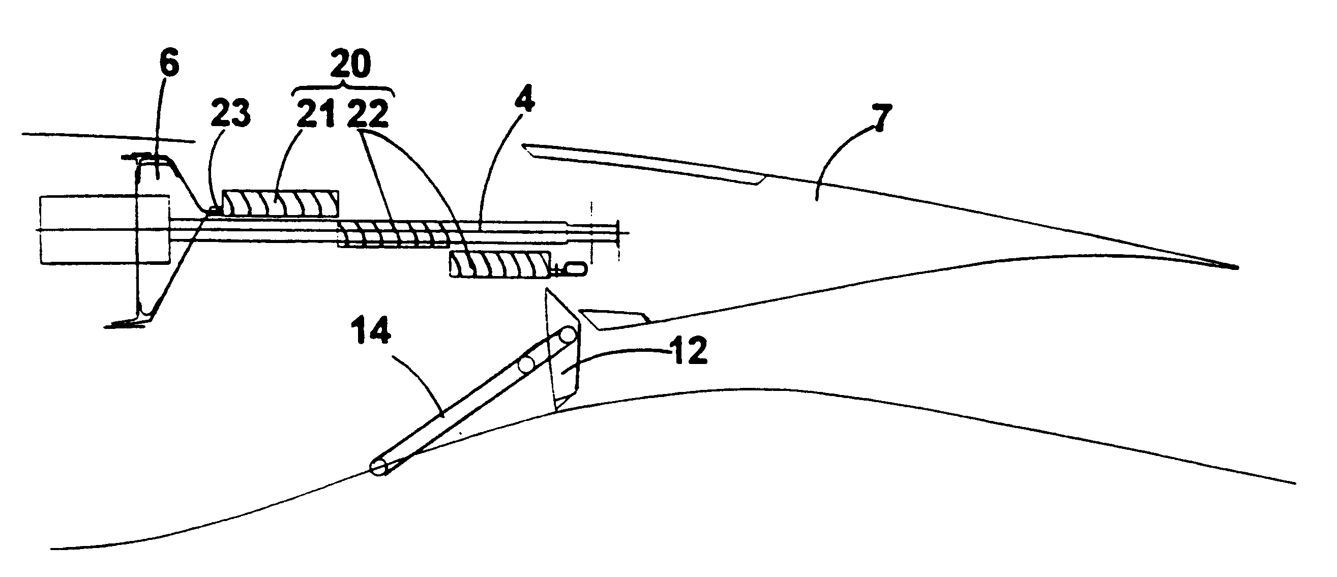
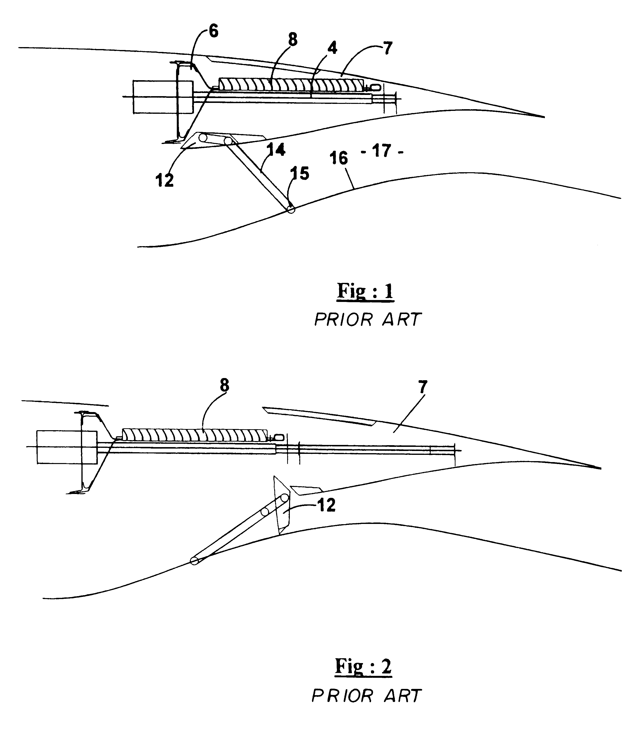
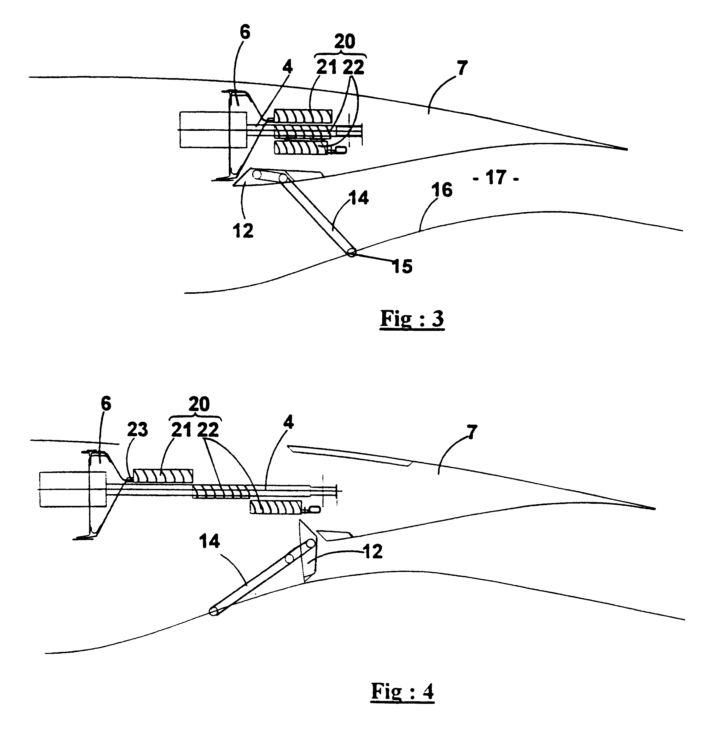
In the embodiment illustrated in FIGS. 3 and 4, the principal difference from Figs. l01 and 2 is that there is a plurality of thrust reverser baffle portions (20). The plurality of flow deflecting baffles comprise two portions: stationary baffle portion (21) and at least one movable baffle portion (22). Two movable baffle portions are illustrated as an example. In both the forward and reverse thrust positions, the stationary baffle portion (21) and the movable baffle portions (22) are substantially parallel to one another. The 15 stationary baffle portion (21) has a first end rigidly connected to an upstream edge of the stationary structure (6), whereas the movable baffle portions (22) are axially movable by a displacement mechanism (4). The displacement mechanism (4) comprises a linear actuator that has, in known fashion, an extendible and retractable rod attached to the displaceable structure (7).

When in a forward thrust position, illustrated in FIG. 3, the stationary baffle porti...


PUM


Abstract

A thrust reverser for a turbofan jet engine having a stationary structure defining an upstream part of a fan cowling and an axially displaceable, annular structure located downstream of the stationary structure, wherein the inner surface of the fan cowling is spaced from an outer surface of an engine cowling to form an annular duct. A plurality of flaps form a portion of the inner surface of the fan cowling during a forward thrust position, and in a reverse thrust position, the flaps pivotably rotate about a stationary pivot so that their first edges are adjacent with the outer surface of the engine cowling to block the annular duct. A plurality of thrust reverser baffle portions are covered by the flaps during the forward thrust position, and during the reverse thrust position, the thrust reverser baffle portions cover a passageway in the fan cowling between the stationary structure and the displaceable structure. The plurality of thrust reverser baffle portions are radially offset and substantially parallel, and comprise a stationary baffle portion and at least one movable baffle portion. In a reverse thrust position, the movable baffle portions are displaced so that the plurality of thrust reverser baffles are longitudinally juxtaposed, redirecting the deflected gas flow.

Description

1. Field of the InventionThe present invention relates to a thrust reverser for a bypass turbojet-engine, and more particularly, a thrust reverser having rotatable pivoting flaps closing an annular gas flow duct and stationary baffle portions radially offset with movable baffle portions redirecting a gas flow.2. Related ArtTurbofan-type turbojet engines typically comprise a turbojet engine encased in a cowling wherein the engine drives a fan usually located at the front portion of the engine. The fan blades are enclosed in a fan cowling so that at least a portion of the is fan cowling is spaced from the engine cowling to define a generally annular gas flow duct. The annular gas flow duct channels the air impelled by the rotation of the fans.As shown in FIGS. 1 and 2, it is known to position a thrust reverser so as to act against the gases flowing through the annular duct. FIG. 1 illustrates a thrust reverser in a forward thrust position having a displaceable structure (7) with an in...

Claims


Application Information

Patent Timeline
IPC IPC(8): F02K1/72F02K1/00
CPCF02K1/72Y02T50/671Y02T50/60
Inventor LECORDIX, JEAN-LOICSCHREIBER, LAURENT CLAUDE JACQUES
Owner SN DETUDE & DE CONSTR DE MOTEURS DAVIATION S N E C M A
Why Eureka
Try Eureka