Rotary ramjet turbo-generator

a rotary ramjet and turbo-generator technology, which is applied in the direction of rocket engine plants, machines/engines, composite engine plants, etc., can solve the problems of severe limits on the performance of a conventional gas turbine engine, limited mass-specific power achievable, and limited high-temperature material performance, etc., to achieve greater mass-specific power, facilitate higher thermal efficiency, and prolong service life

Active Publication Date: 2007-03-15
RGT UNIV OF MICHIGAN
View PDF11 Cites 52 Cited by
  • Summary
  • Abstract
  • Description
  • Claims
  • Application Information

AI Technical Summary

Benefits of technology

[0016] By reversing the relative positions of the rotor and stator in comparison to the prior art rotary ramjet teachings, it becomes possible to fabricate the rotor from materials capable of withstanding higher temperatures than those achievable in prior art designs. In practical terms, this “inside-out” orientation of components, wherein the rotor is positioned about the exterior of the stator, facilitates higher thermal efficiency, greater mass-specific power, longer service life, and reduced fabrication cost relative to conventional gas turbine engine teachings and relative to prior art rotary ramjet engine teachings. These advantages are realized in applications of any scale, and the novel arrangement facilitates miniaturization of a rotary ramjet engine in applications where miniaturization would be advantageous.
[0017] The invention also comprises a method for operating an inside-out Brayton-cycle rotary ramjet engine within the confines of a helically elongated pass-through combustion chamber formed between a preferably stationary radially outward surface and a rotating flow channel. The method comprises the steps of fixedly supporting the radially outward surface about a central axis, rotatably supporting a helical ramjet flow channel about the central axis and concentrically axially aligned with the radially outward surface, and rotating the flow channel in a circular path positioned on the exterior of the radially outward surface. For the reasons stated above, by orbiting the rotor so that it is positioned about the exterior of the stator, i.e., by employing this “inside-out” design, greater engine efficiencies can be achieved through the use of desirable materials which have high operating temperature capabilities. This results in dramatically higher thermal efficiency, greater mass-specific power, longer service life, and reduced fabrication cost relative to conventional gas turbine engines and relative also to prior art rotary ramjet engines. These novel concepts are adaptable in applications of any scale, and facilitate miniaturization of the rotary ramjet engine if desired.

Problems solved by technology

Most of the mass in such a conventional system results from the bladed compressor and turbine, which in turn limits the mass-specific power achievable.
Additionally, the need for a bladed compressor and turbine introduces severe limits on the performance of a conventional gas turbine engine.
These limits stem from the high-temperature material limitations associated with the first-stage turbine blades.
In particular a bladed turbine must be made from a material with good mechanical properties but relatively poor thermal properties which in turn imposes strict limits on the maximum turbine inlet temperature, and thus on the maximum combustor exit temperature.
This practical limitation imposed by the material characteristics in the first-stage turbine blades lowers both the thermal efficiency and the power achievable from the conventional approach.
However, miniaturization of conventional, large-scale turbine engines while maintaining comparably high operational performance has to date proven difficult.
Most engineering issues encountered in large-scale gas turbines, such as the need to maintain acceptable compressor and turbine blade tip clearances, are even more difficult to address at small scales.
The need for high-efficiency multi-stage bladed compressors and turbines also contributes significantly to the complexity and overall cost of producing small-scale turbine engines and generators based on miniaturization of conventional large-scale systems, and furthermore ultimately limits the service life of such engines.
However, conventional ramjet engines can only be used when the forward speed of the engine is sufficiently high relative to the surrounding air to produce suitable ram pressure which is needed for acceptable performance.
However, the prior art rotary ramjet configurations have numerous disadvantages that have to date prevented successful realization for lack of useful operating performance.
Just like in a bladed turbine engine, the resulting large tensile stresses in the rotating parts of a ramjet engine prevent high-temperature materials from being used to fabricate the rotor used in the ramjet flow channel because the ceramic material would likely fail in tension mode.
A further characteristic of the desirable high-temperature materials is that they typically have far greater compressive strength than tensile strength, and in particular fail far more readily in tension than do the kinds of materials found in conventional bladed turbine engines.
The trade-off is unfortunate, because higher tensile strength materials cannot sustain high-temperatures, and therefore the maximum combustor exit temperatures (T3) which can be sustained in the prior art systems are substantially low relative to a stoichiometric ideal.
Since the combustor exit temperature is a key factor in determining the power output and efficiency of a Brayton-cycle engine, the inability to use high-temperature materials (like ceramics) is a serious disadvantage of all prior art systems.

Method used


Image

  • Rotary ramjet turbo-generator
  • Rotary ramjet turbo-generator
  • Rotary ramjet turbo-generator

Examples


Embodiment Construction

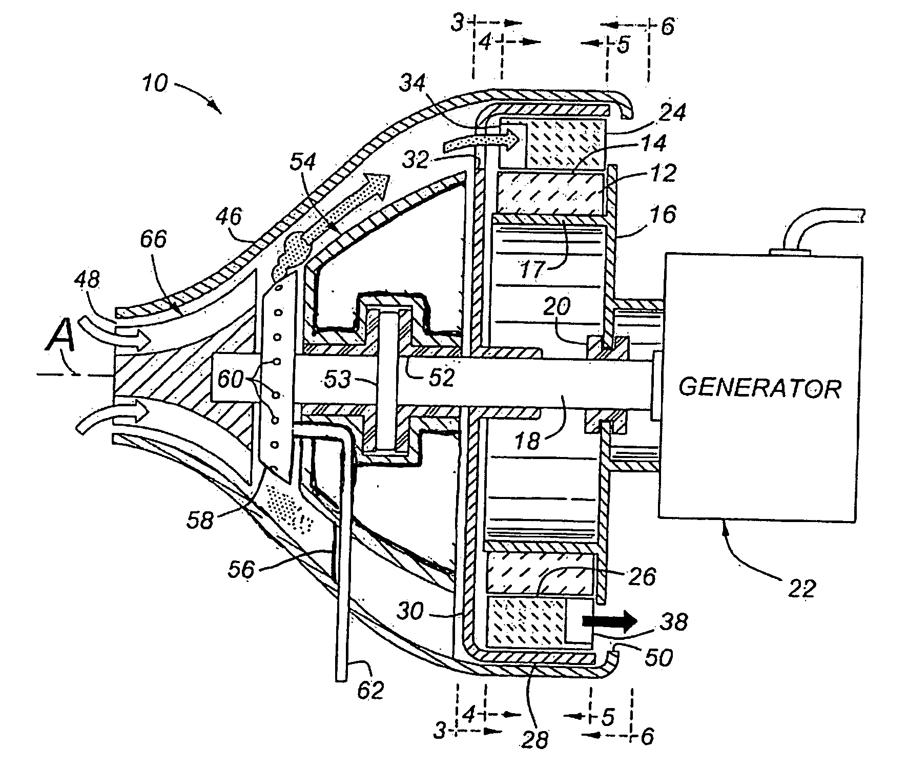
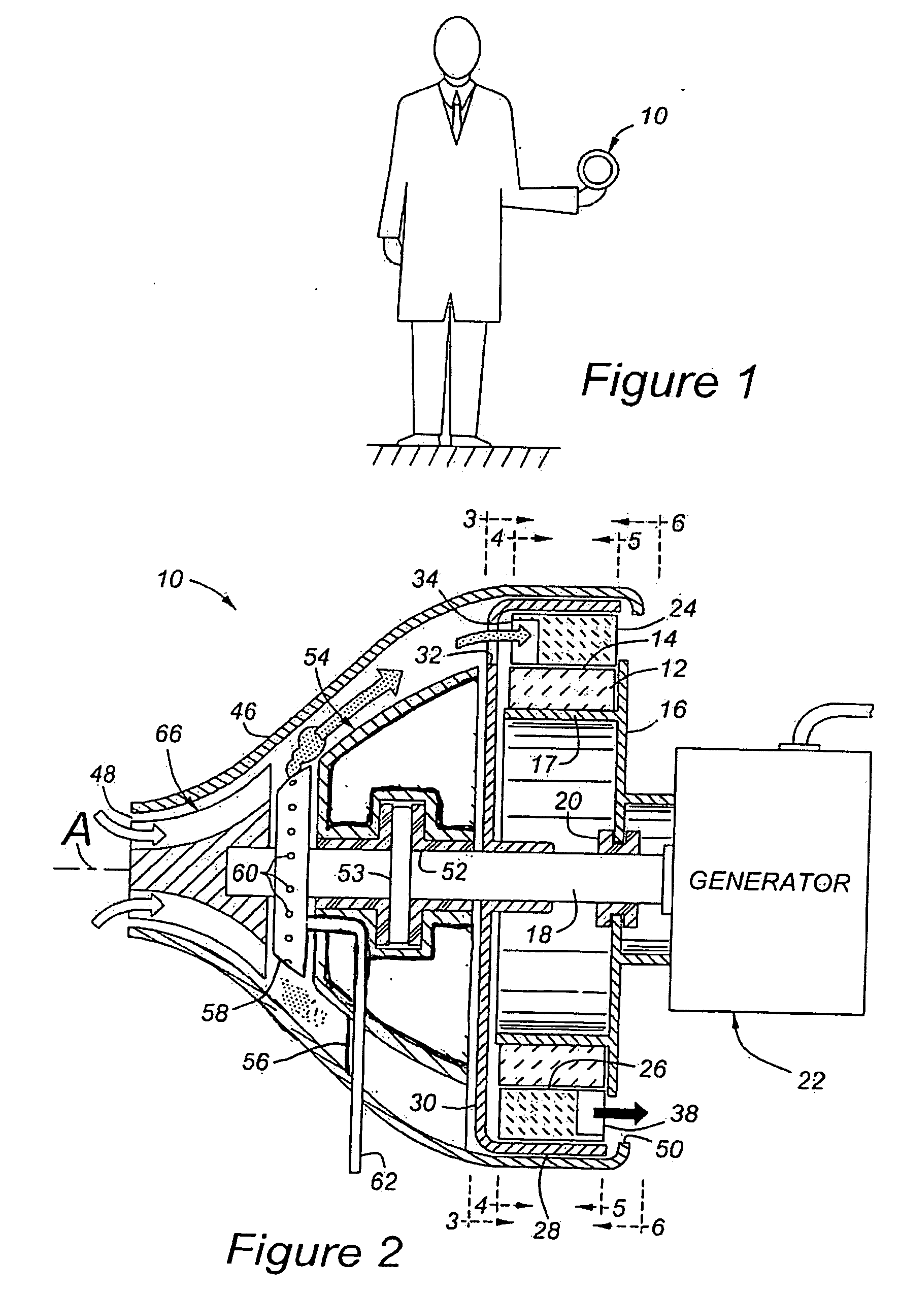
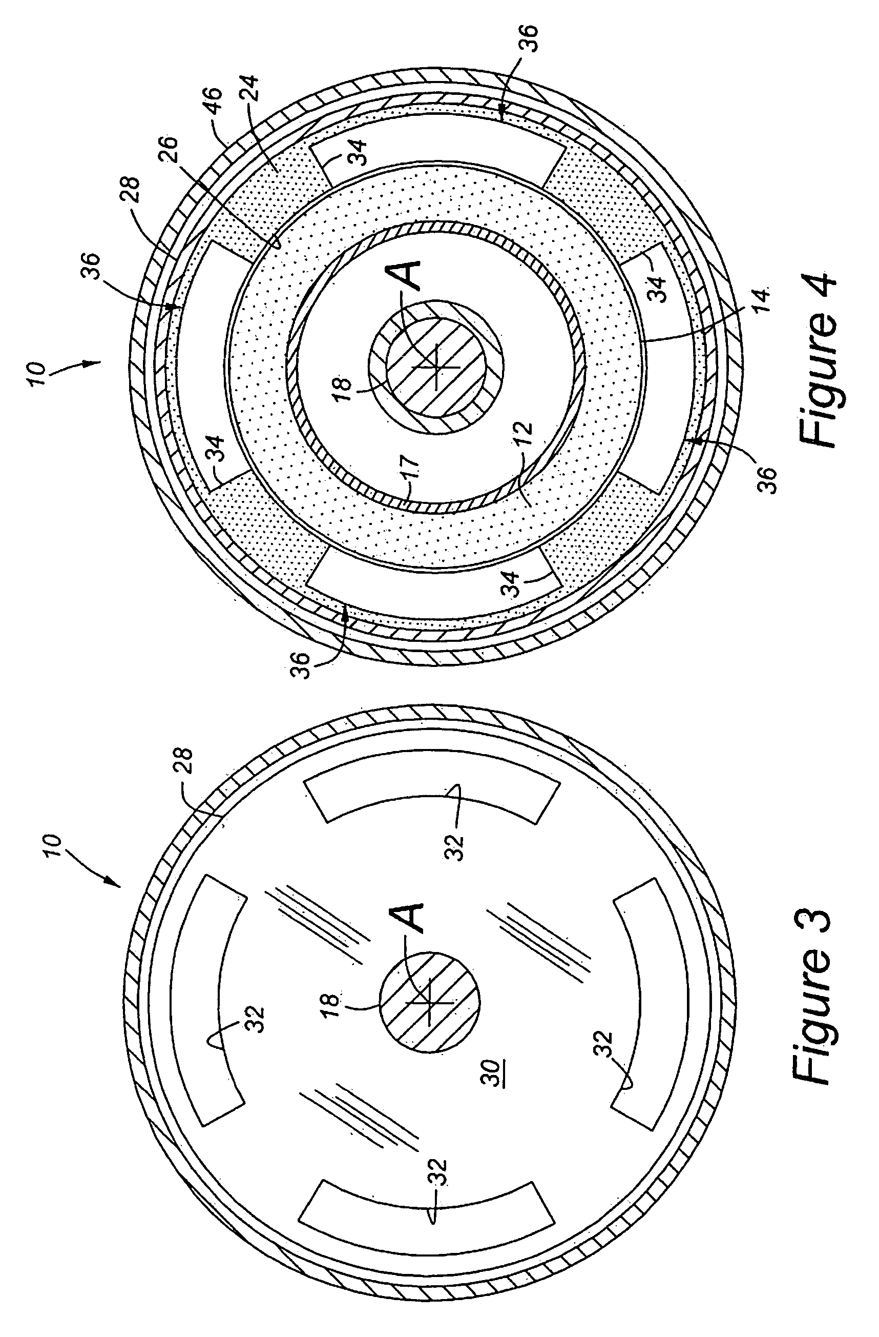
[0030] Referring to the Figures, wherein like numerals indicate like or corresponding parts throughout the several views, an inside-out Brayton-cycle rotary ramjet engine according to the subject invention is generally shown at 10 in FIGS. 1 and 2. The ramjet engine 10 is of the type which can be scaled to fit any application, from large-scale power generation units producing electricity in the megawatt ranges, to small-scale engines and turbo-generators producing less than 1000 watts shaft power. The engine 10 includes a stator 12 which has a generally annular, radially outward surface 14 centered about a central axis A. In the preferred embodiment, the stator 12 is stationary, but could be configured to rotate with or against the rotor 24. This outward surface 14 of the stator 12 may be generally cylindrical, as depicted in the Figures, or may be conically tapered or contoured in some fashion to provide optimal performance. Preferably, the stator 12 comprises a ring-like construct...


PUM


Abstract

A Brayton-cycle rotary ramjet engine (10) operated within the confines of a helically elongated pass-through duct formed between a preferably stationary radially outward surface (14) and an outer rotating flow channel (36). The flow channel (36) is contoured between its inlet (34) and outlet (38) to include a supersonic diffuser (40), a combustor (42) and an expansion nozzle (44). Gaseous fuel, or liquid fuel atomized by a fuel slinger (58) within a housing (46), or solid fuel in the form of fine particulates, is inter-mixed with an oxidizer prior to being directed to the flow channel inlets (34). The air and fuel are combusted in the flow channels (36) and exhausted through the rear of the housing (46). A generator (22) can be coupled to a power shaft (18) to convert net shaft power into electricity. Preferably, the rotor (24) and stator (12) are fabricated from a ceramic or other high-temperature material so that combustor exit temperatures (T3) can be operated at highly efficient levels.

Description

CROSS-REFERENCE RELATED APPLICATIONS [0001] This application claims priority to U.S. Provisional Application No. 60 / 715,499 filed Sep. 9, 2005.BACKGROUND OF THE INVENTION [0002] 1. Field of the Invention [0003] The invention relates generally to a gas turbine engine / generator, and more particularly toward a rotary ramjet turbo-generator. [0004] 2. Related Art [0005] In a traditional Brayton-cycle gas turbine engine, a bladed compressor first compresses air, which then mixes and burns with a fuel like jet fuel, kerosene, natural gas or propane in a combustor. The heat that comes from the burning fuel expands the combustion product gases. As these hot product gases flow at high speed through a bladed turbine, a torque is produced on a turbine shaft. The torque is used to drive the compressor and possibly one or more external implements like a generator. These conventional Brayton-cycle engines require a bladed compressor, driven by a bladed turbine, to achieve the high compression rat...

Claims


Application Information

Patent Timeline
Patent Type & Authority Applications(United States)
IPC IPC(8): F02K7/10
CPCF02K7/16F05D2250/82Y02T50/671Y02T50/60
Inventor DAHM, WERNER J.A.
Owner RGT UNIV OF MICHIGAN
Why Eureka
Try Eureka