Cast unitized primary truss structure and method

a primary truss and cast technology, applied in the field of truss structures, can solve the problems of large cast support structures traditionally not being used, monolithic structural support elements formed from casting processes, and unsatisfactory use as primary components, and achieve the effect of more weight efficiency and cost-effective production

Active Publication Date: 2005-12-15
THE BOEING CO
View PDF4 Cites 55 Cited by
  • Summary
  • Abstract
  • Description
  • Claims
  • Application Information

AI Technical Summary

Benefits of technology

[0007] The present invention is directed to a truss structure that is suitable for use in commercial aircraft applications, but is not limited to such applications. The truss structure is cast as a single piece component from a lightweight, yet structurally strong material. In one preferred form the material is a titanium alloy. The truss structure is well suited for use as an engine strut on large commercial aircraft. Since the truss structure creates an integrally formed, single component part, it is more cost effective to produce, and more weight efficient than previously employed engine strut assemblies that involve hundreds of independent component parts held together by thousands of independent fasteners.
[0009] A principal feature of the truss structure is that it is cast from a lightweight material, and in one preferred form from a titanium alloy, as a single piece, integrally formed structure. The elongated rails and truss elements of the structure are further arranged in consideration of the loads that will be experienced by the engine strut during operation of the aircraft, and more specifically to eliminate, or virtually eliminate, the risk of structural failure of the truss structure should one particular truss element develop a crack. Thus, the truss structure is designed to provide redundant load paths to better ensure that if a crack develops in any one particular truss element, the entire truss structure will still remain structurally sound.

Problems solved by technology

Large cast support structures have traditionally not been used in applications where fail-safe performance of the structure is required.
It has generally been believed that a monolithic structural support element, formed from a casting process, is not ideal for use as a primary component of an aircraft because of heretofore recognized inherent limitations with large, cast structures.
More particularly, with previously developed large, cast structures, when such structures develop a crack, the crack may propagate through the structure in response to repeated cyclic loading on the structure.
Thus, a failure beginning in one element of a large, cast support structure can eventually result in the failure of the entire structure.
Further limitations with large, cast structures involve the weight typically associated with such structures.
In aircraft applications, where weight is of paramount importance, casting a large truss-like support structure from steel would yield a component that is simply unacceptably heavy.
Some large structural parts have been cast from aluminum, but aluminum also has drawbacks when attempting to apply it to components to be used with aircraft structures.
Most notably, aluminum is not suitable for areas of an aircraft where the component will experience high heat, such as an engine pylon, which experiences significant heat generated by the jet engine.
The cost of just the engine strut is a significant portion of the total cost of manufacturing an aircraft despite the structure being a relatively small fraction of the aircraft's total mass.

Method used


Image

  • Cast unitized primary truss structure and method
  • Cast unitized primary truss structure and method
  • Cast unitized primary truss structure and method

Examples


Embodiment Construction

[0020] The following description of the preferred embodiment(s) is merely exemplary in nature and is in no way intended to limit the invention, its application, or uses.

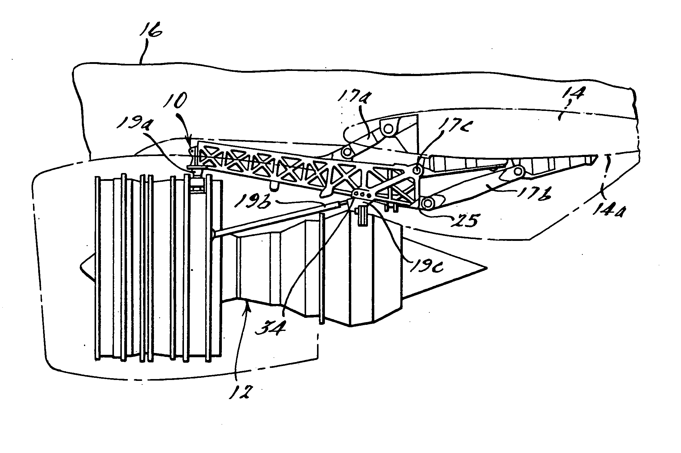
[0021] Referring to FIG. 1, there is shown a simplified illustration of a truss structure 10 in accordance with a preferred embodiment of the present invention specifically adapted for use as an engine strut or pylon on a commercial aircraft. The truss structure 10, in this example, is used to secure a jet engine 12 to an under surface 14a of a wing 14 of a commercial aircraft 16 via links 17a and 17b. Links 19a, 19b and 19c secure the jet engine 12 to the truss structure 10.

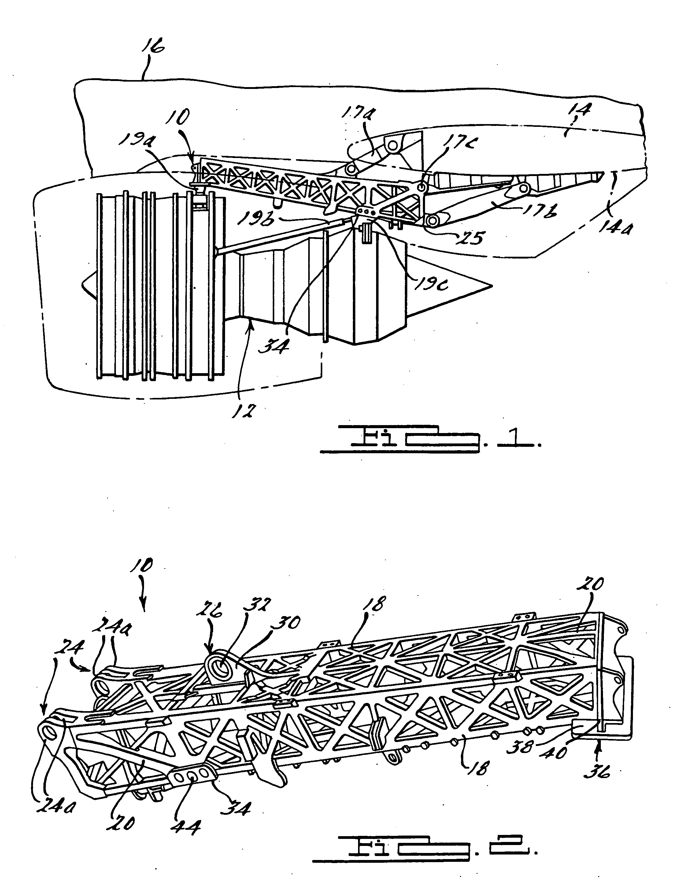
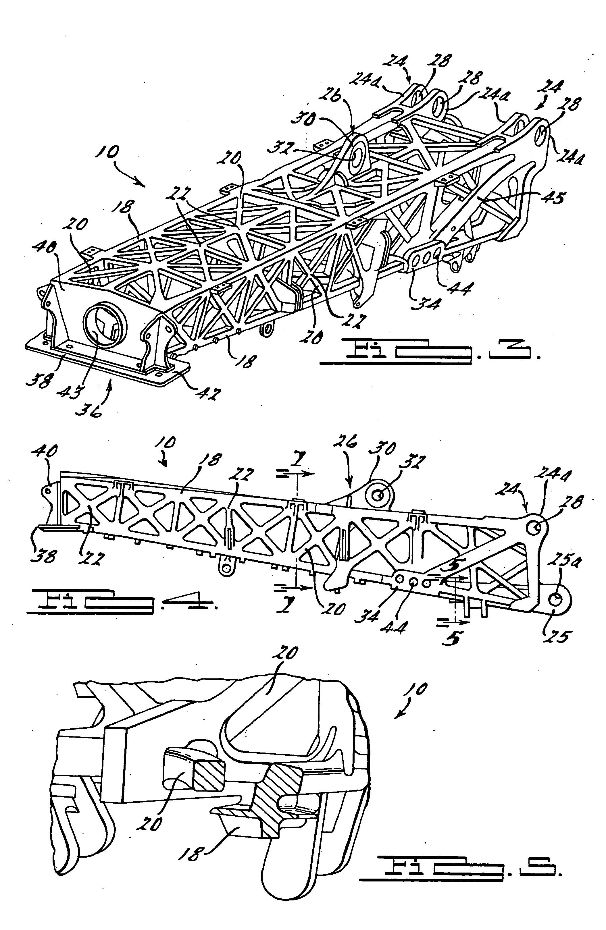
[0022] Referring to FIGS. 2-4, the truss structure 10 is shown in greater detail. The truss structure 10 includes a plurality of elongated, tubular rails 18 arranged to form an overall generally rectangular shaped piece when viewed from one end of the truss structure 10. The elongated rails 18 are preferably either circular in cross-section or ...


PUM

PropertyMeasurementUnit
temperatureaaaaaaaaaa
structureaaaaaaaaaa
thicknessaaaaaaaaaa

Abstract

A truss structure well suited for use as an engine strut on a commercial aircraft. The truss structure is cast as a single piece integrally formed component from a titanium alloy or another suitably lightweight, structurally strong material. The truss structure includes a plurality of integrally formed attachment structures which enable the truss structure to be secured to an element of an aircraft such as a wing. A plurality of attachment areas for an element such as an engine is also formed that allows the element (e.g. jet engine) to be secured to the truss structure. The truss structure includes a plurality of elongated rails and truss elements that are arranged to provide redundant load paths to ensure that a failure of any one truss element or elongated rail will not result in a failure of the overall truss structure to support whatever load is required.

Description

FIELD OF THE INVENTION [0001] This invention relates to truss structures and, more particularly to a monolithic, cast truss suitable for forming a primary structure for a mobile platform such as an aircraft. BACKGROUND OF THE INVENTION [0002] Large cast support structures have traditionally not been used in applications where fail-safe performance of the structure is required. One example of such an application would be in connection with the manufacture of large commercial aircraft. In such instances, large support structures, and particularly large support structures such as engine pylons, have been constructed with a large plurality of independent parts and fastening elements designed so that the failure of any one of the constituent parts does not result in failure of the entire structure. It has generally been believed that a monolithic structural support element, formed from a casting process, is not ideal for use as a primary component of an aircraft because of heretofore rec...

Claims


Application Information

Patent Timeline
Patent Type & Authority Applications(United States)
IPC IPC(8): B22C9/22
CPCB22C9/22B64D27/26B64D2027/264
Inventor HUGGINS, GEORGE L.MEYER, BRIAN J.POST, LEE J.CROOK, GORDON R.NELSON, SCOTT N.KAMPF, STANLEY T.HEITMANN, AARON R.WARDAK, HAFIZULLAHALLISON, DANIEL J.CAMENZIND, JOSEPH W.
Owner THE BOEING CO
Why Eureka
Try Eureka