Thrust reverser with grids for jet engine

a jet engine and thrust reverser technology, applied in the field of thrust reversers, can solve the problems of increasing the pressure in the engine, difficult to manage the speed of the turbofan, and numerous aerodynamic disturbances, and achieve the effect of maintaining the simplicity and lightness of means

Inactive Publication Date: 2010-06-10
SAFRAN NACELLES
View PDF6 Cites 51 Cited by
  • Summary
  • Abstract
  • Description
  • Claims
  • Application Information

AI Technical Summary

Benefits of technology

[0022]The present invention aims to avoid these disadvantages while maintaining the simplicity and lightness of the means used to drive the flap, and accordingly consists of a thrust reverser for a jet engine, as set forth in the introduction, wherein furthermore a slider for driving the flap is movably mounted in at least one translation-guiding track formed in a structure of the slidi

Problems solved by technology

A first problem with such a configuration concerns the kinetics of the degree of opening of the flaps which, at the start of the opening phase of the movable cowls, is quicker than the opening of said cowl.
This results in an increase in the pressure in the engine, thereby entailing difficult management of the turbofan speed in this transient phase.
A second problem concerns the guide links passing through the duct and thereby causing numerous aerodynamic disturbances in the secondary flow.
Fastening the links to the internal structure constitutes a third problem.
Specifically, the installation of fixed hinge points reduces the area of the internal structure that can be used for acoustically treating said internal structure.
Finally, a fourth problem concerns the fact that the thrust reverser structure is mechanically connected by the links to the internal structure.
As a result, the thrust reverser structure and the internal structure are not independent of one another, thus complicating their removal when maintenance operations on the nacelle or the turbofan make this necessary.
It should be pointed out that this problem more particularly concerns internal structures of the so-called “O-duct

Method used


Image

  • Thrust reverser with grids for jet engine
  • Thrust reverser with grids for jet engine
  • Thrust reverser with grids for jet engine

Examples


Embodiment Construction

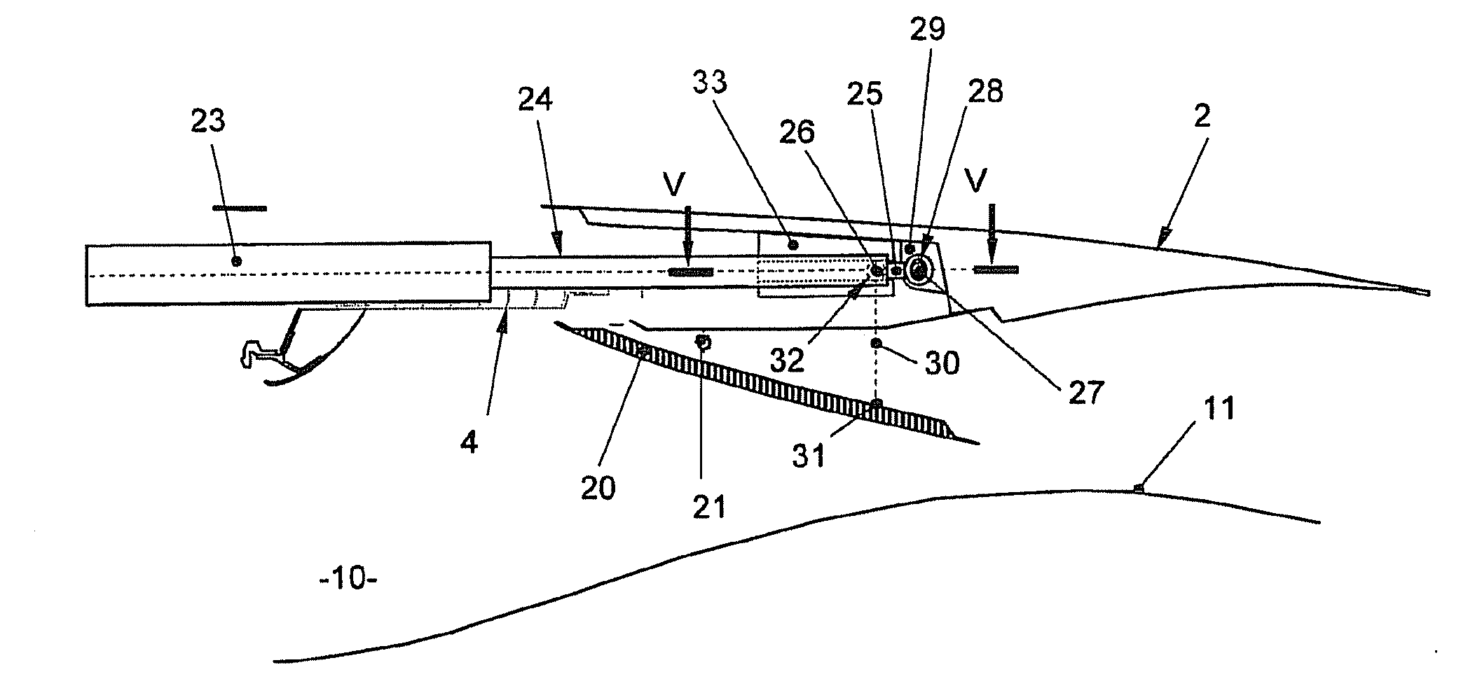
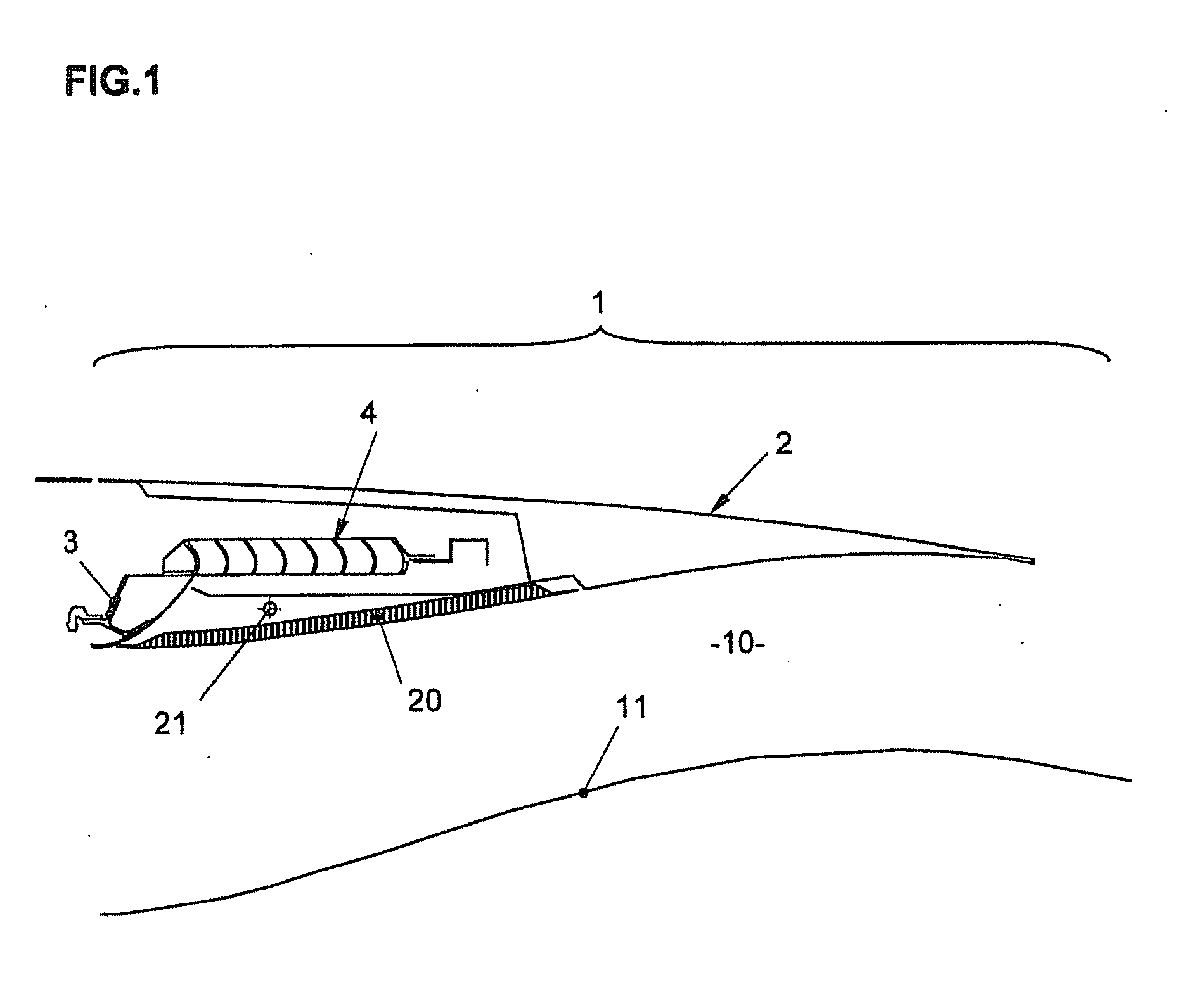
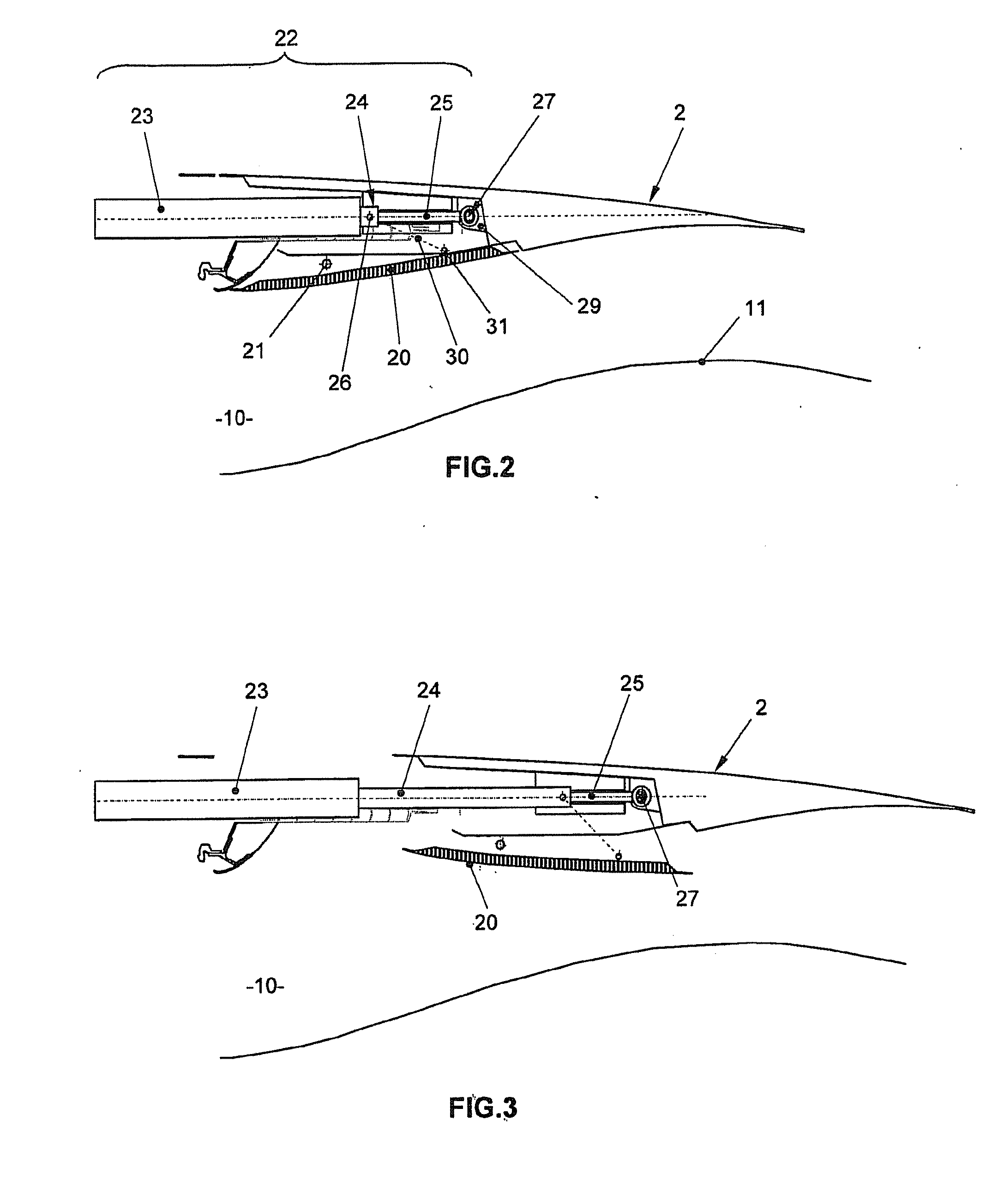
[0049]In a manner known per se, the thrust reverser 1 shown in FIGS. 1 to 12 is associated with a turbofan (not shown) and comprises an external nacelle which, together with a concentric internal structure 11, defines an annular flow duct 10 for a secondary flow stream.

[0050]A longitudinally sliding cowl 2 is formed by two semicylindrical portions mounted on the nacelle so as to be able to slide along tracks (not shown).

[0051]An opening provided with fixed deflection grids 4 is formed in the external nacelle of the thrust reverser 1. In a situation with direct thrust of the gases, this opening is closed by the sliding cowl 2 and it is exposed, in a thrust reversal situation, by a longitudinal translational movement of the sliding cowl 2 in the downstream direction (with respect to the direction of flow of the gases).

[0052]A plurality of reversal flaps 20, distributed over the circumference of the cowl 2, are each pivotally mounted, by an upstream end about a hinge pin 21, to the sli...


PUM


Abstract

The invention relates to a thrust reverser (1) comprising an opening with fixed grids (4) that is closed by a sliding lid (2) in case of direct thrust, and opened by the downstream longitudinal translation displacement of the lid (2) in case of thrust reversal. A flap (20) is pivotally mounted at one upstream end on the lid (2) and can move between a retracted position and an expanded position in which, in case of thrust reversal, it blocks an annular channel (10) in order to redirect a gas flow towards the grid opening (4). A slider (24) for driving the flap (20) is mounted so as to be capable of displacement in at least one translation guiding rail (33) provided in the structure of the lid (2), and is connected to a downstream end of the flap (20) through a driving connecting rod (30) so that a translation movement of the slider (24) in the guiding rail (33) results in a pivoting of the connecting rod (30) and of the flap (20). Actuation means (22) are provided for driving the slider (24) in a translation movement in the guiding rail (33) when the lid (2) is in a downstream translation phase.

Description

FIELD OF THE INVENTION[0001]The invention relates to a thrust reverser, known as a grid-type or cascade-type thrust reverser, for a jet engine.BACKGROUND OF THE INVENTION[0002]An aircraft is moved by a number of jet engines each housed in a nacelle which also accommodates a set of auxiliary actuating devices which are associated with the operation of said aircraft and which perform various functions when the jet engine is operating or at a standstill. These auxiliary actuating devices particularly comprise a mechanical thrust reversal system.[0003]A nacelle generally has a tubular structure comprising an air inlet upstream of the jet engine, a mid-section intended to surround a fan of the jet engine, and a downstream section accommodating the thrust reversal means and intended to surround the combustion chamber of the jet engine, and is generally terminated by an exhaust nozzle whose outlet is situated downstream of the jet engine.[0004]Modern nacelles are intended to accommodate a ...

Claims


Application Information

Patent Timeline
IPC IPC(8): F02K3/02F16H21/50
CPCF02K1/72Y10T74/18808F05D2260/50F02K1/763Y02T50/60
Inventor VAUCHEL, GUY BERNARDBAUDU, PIERRE ANDRE MARCEL
Owner SAFRAN NACELLES
Why Eureka
Try Eureka