Frameless to frame-based registration system

a registration system and frameless technology, applied in the field of frame-based " stereotaxy, can solve problems such as patient discomfor

Inactive Publication Date: 2001-07-10
INTEGRA BURLINGTON MA
View PDF8 Cites 154 Cited by
  • Summary
  • Abstract
  • Description
  • Claims
  • Application Information

AI Technical Summary

Problems solved by technology

This causes some discomfort for the patient and is an added step.

Method used


Image

  • Frameless to frame-based registration system
  • Frameless to frame-based registration system
  • Frameless to frame-based registration system

Examples


Embodiment Construction

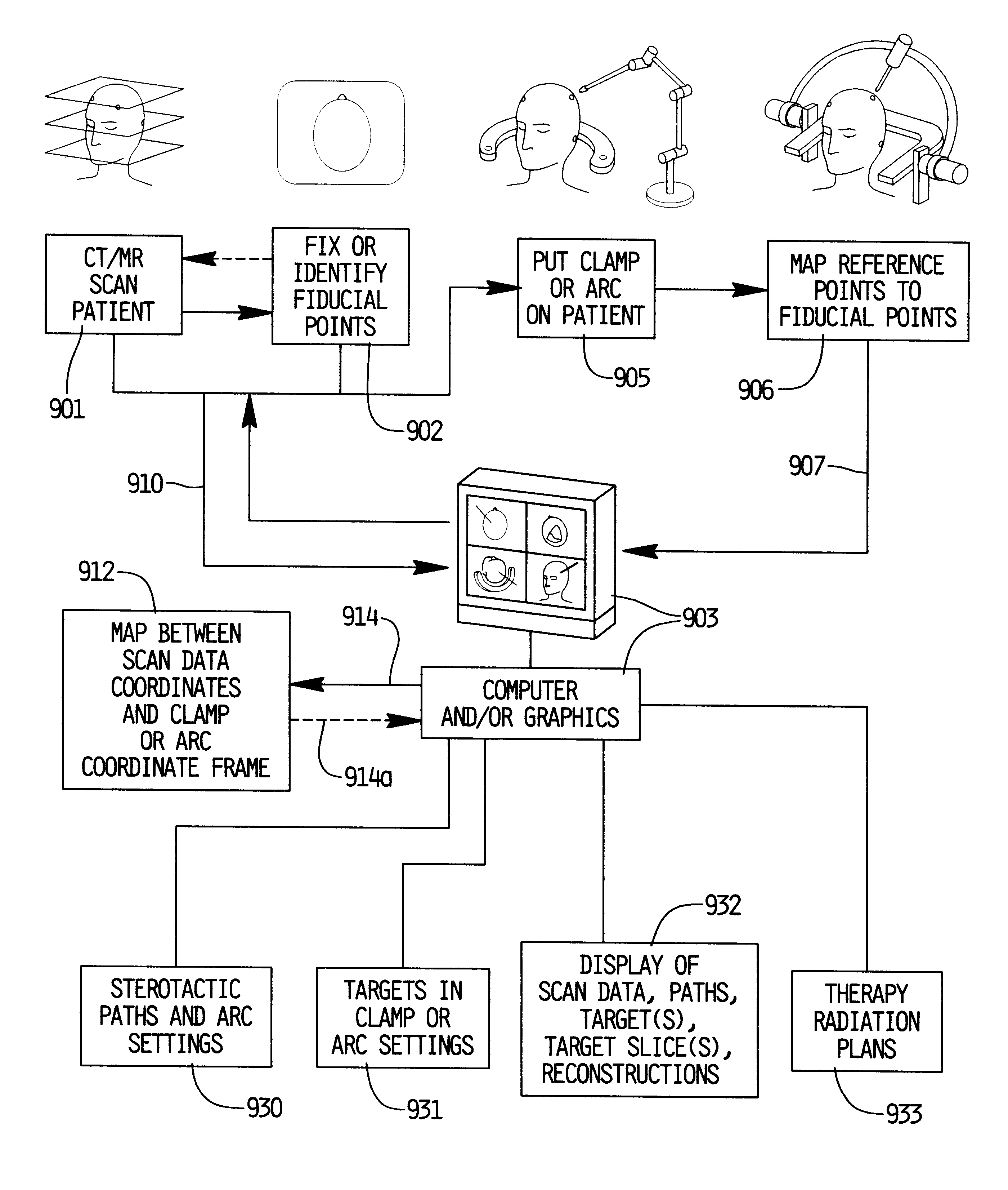
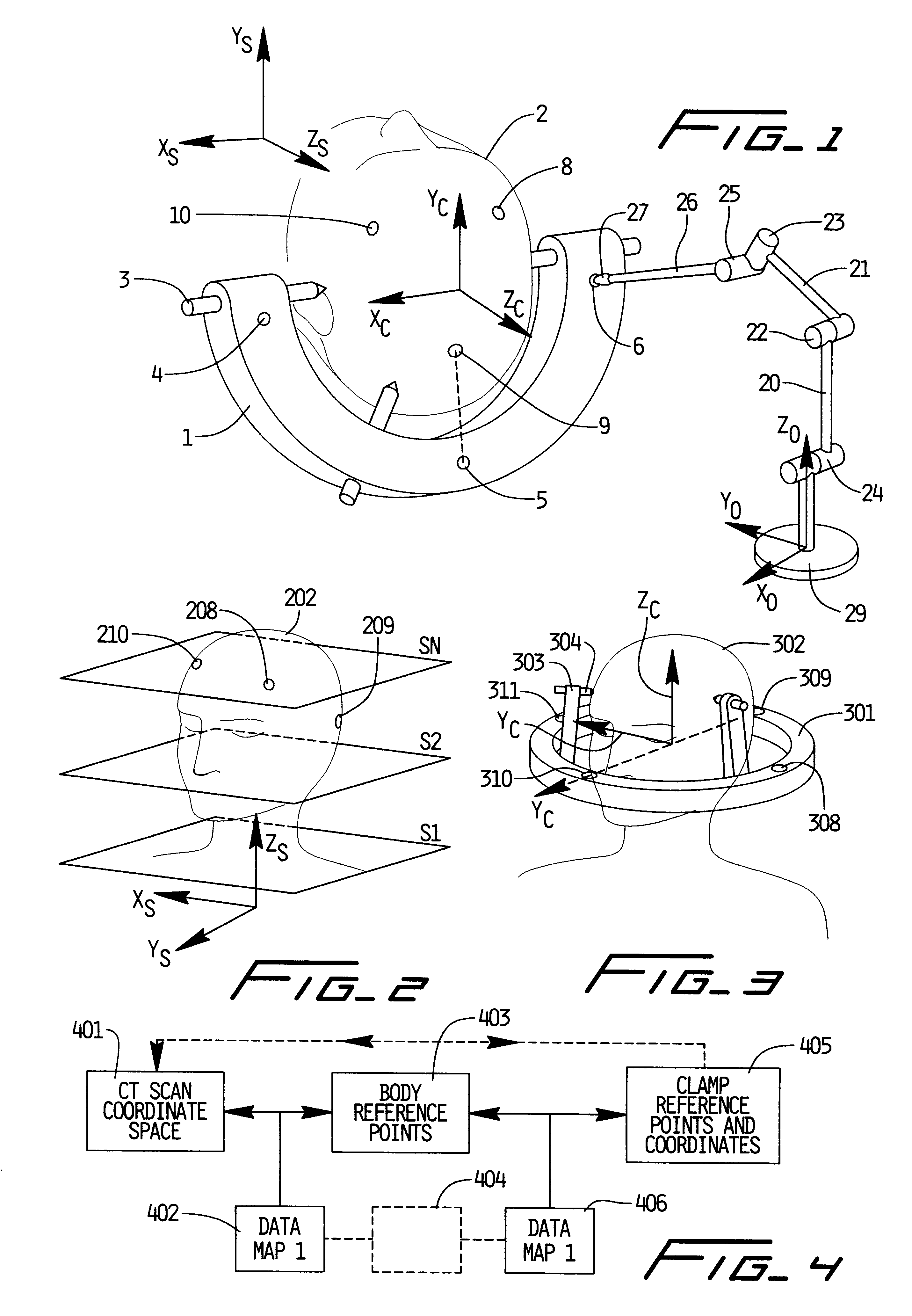
Referring to FIG. 1, a head clamp 1 is secured to the patient's anatomy 2 (in this case, the head) by means of a series of head screws 3. This would be a typical setting in an operating room where a surgical head clamp is applied to a patient's skull for a neurosurgical operation. As part of the embodiment of this invention, the head clamp has a series of reference points (4, 5, and 6, in this example), which are at known coordinate positions relative to a coordinate system indicated by the arrows X.sub.c, Y.sub.c, and Z.sub.c associated with the head clamp 1. This coordinate system can be referred to as the stereotactic coordinate system of the head clamp. Referring to FIG. 2, the patient's anatomy 22 is scanned by an image scanner such as a CT tomographic scanner which can utilize either X-rays, MRI imaging, P.E.T. imaging, etc. to produce a series of image planes represented by S1, S2, S3, . . . S.sub.N through the patient's body. The scanner has a coordinate system represented b...


PUM


Abstract

This invention involves apparatus and methods for relating image scan data of a patient's anatomy from an imaging scanner to a device attached to said patient's anatomy or to an apparatus located nearby said patient's anatomy. In one embodiment it includes identification of fiducial points or markers on or near the patient's anatomy in the image scan data, and subsequently relating these fiducial points to reference points or structures connected to an apparatus attached to or nearby the patient's body. Such an apparatus might be a surgical head clamp or stereotactic frame or arc which has been attached to the patient's head at the time of surgery. A mapping is made between the coordinate frame data of the scan image to the coordinate reference frame of the patient attachment means or external apparatus by physically referencing the fiducial points to the patient attachment means or external apparatus. In one embodiment, such registration can be in the form of distance or coordinate measurements between the fiducial points on the patient's body and the reference points on the external apparatus. Applications are given in the field of frameless stereotaxy, radiosurgery, and stereotactic frame application.

Description

BACKGROUND TO THE INVENTIONThe field of "frame-based" stereotaxy is now well established. In that field, typically, a head ring is affixed to the patient's head or skull, and a localizer frame with graphic reference means is attached to the head ring. The patient is then scanned in an image scanner, such as a CT scanner, and the fiducial markings in the image scan data from the graphic reference means are used to map the image scan data or the coordinate frame of that image scanner into the coordinate reference frame of the stereotactic head ring. Following that, the patient may typically go to surgery, a calculation or determination of an anatomical target seen in the image scan data is made, and a stereotactic arc system is attached to the head ring to pass a probe to the selected anatomical target. Examples of such systems are the Radionics BRW and CRW Stereotactic Systems. A significant feature of the frame-based system is that the head frame with graphic reference means is atta...

Claims


Application Information

Patent Timeline
Patent Type & Authority Patents(United States)
IPC IPC(8): A61B19/00
CPCA61B19/20A61B19/5244A61B19/203A61B2019/5287A61B2019/5255A61B2019/5272A61B2019/507A61B34/20A61B90/10A61B90/14A61B2034/107A61B2034/2055A61B2034/2072A61B2090/363
Inventor COSMAN, ERIC R.CUNDARI, MICHAEL A.LEDOUX, ROBERT J.DANIELS, ROBERT A.MAUGE, CHRISTOPHE P.LABUZ, JEFFREY
Owner INTEGRA BURLINGTON MA
Why Eureka
Try Eureka