Automatic tank-type flusher

a tank-type, flushing technology, applied in the field of toilet flushing, can solve the problem of reducing the effectiveness of the flush valve seal

Inactive Publication Date: 2001-07-24
ARICHELL TECH INC
View PDF41 Cites 65 Cited by
  • Summary
  • Abstract
  • Description
  • Claims
  • Application Information

AI Technical Summary

Problems solved by technology

Also, high line pressure actually aids in preventing leakage through the flush

Method used


Image

  • Automatic tank-type flusher
  • Automatic tank-type flusher
  • Automatic tank-type flusher

Examples


Embodiment Construction

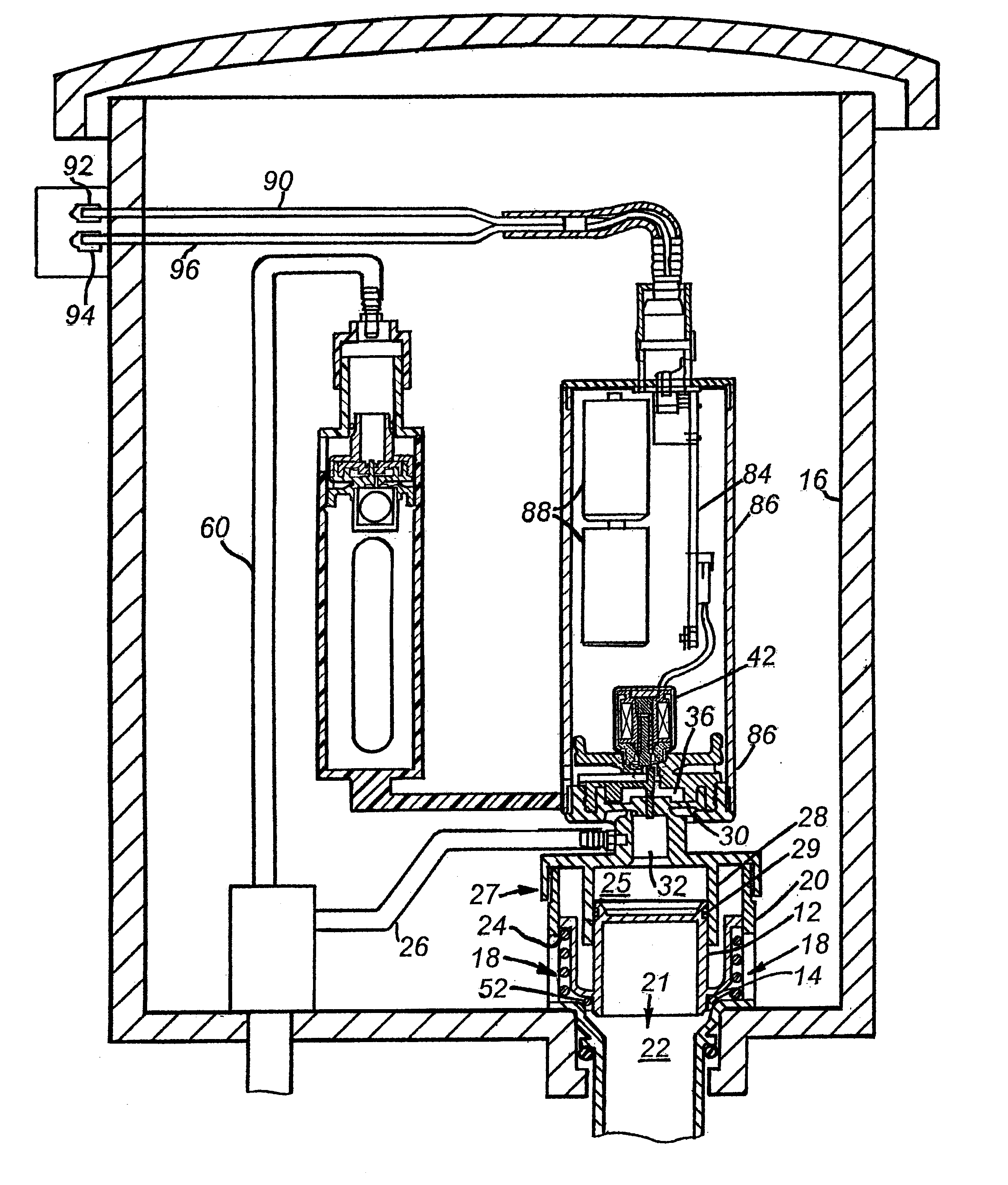
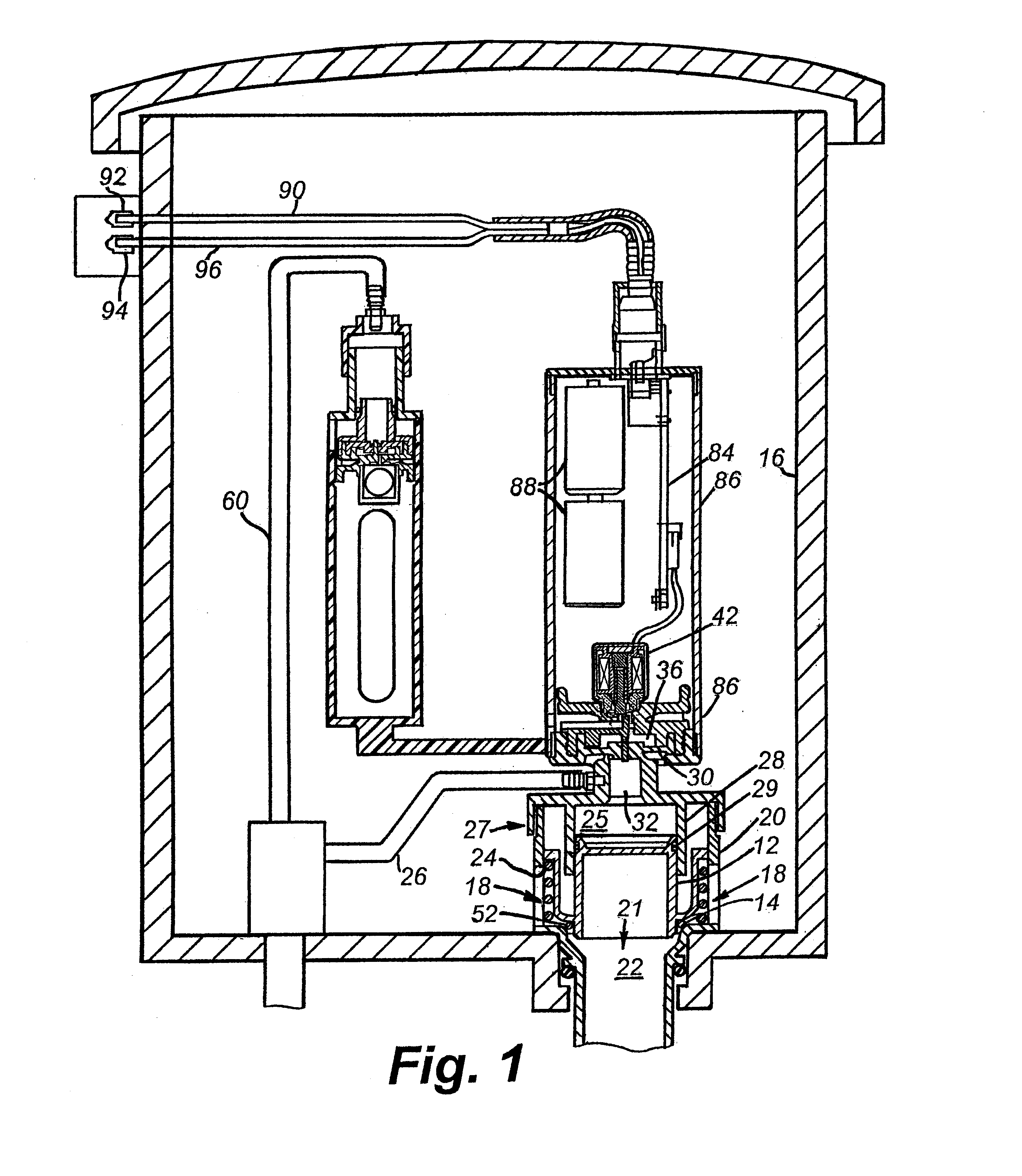
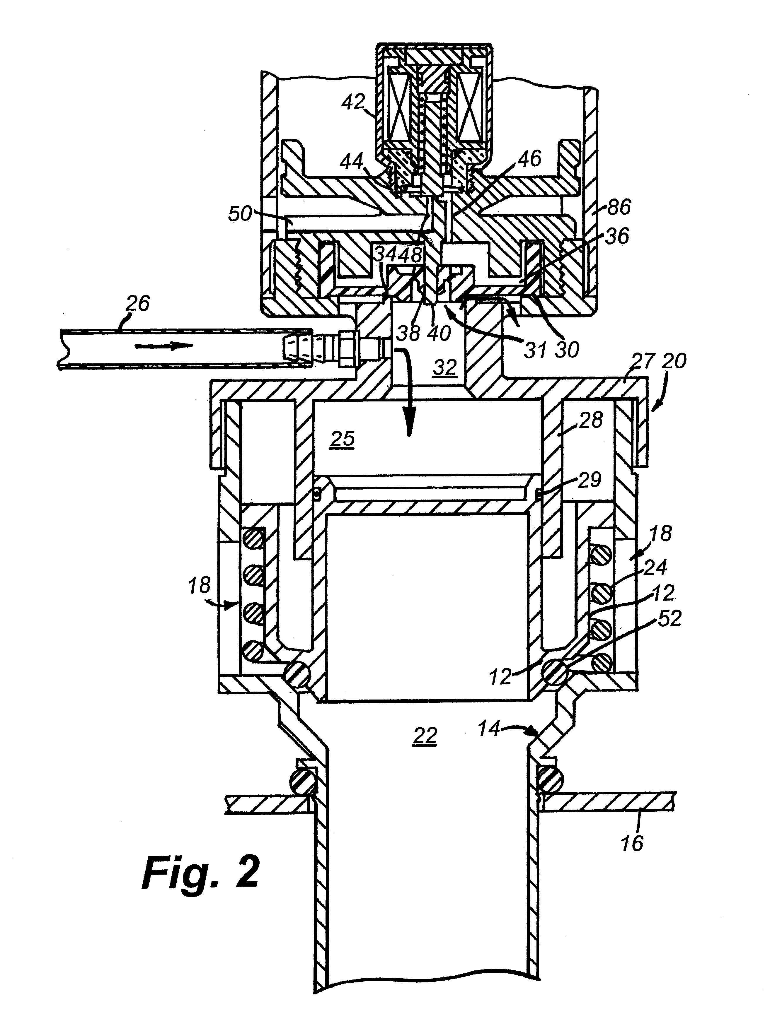
In the state that FIG. 1 depicts, a gravity-type flush mechanism's flush-valve member 12 is seated in a flush-valve seat 14 formed in the bottom of a toilet tank 16. In that seated position, the valve member 12 prevents water from the tank 16 that has entered through flush ports 18 in a flush-valve housing 20 from flowing through a flush outlet 21 and a flush conduit 22 to a toilet.

As FIG. 2 shows, the flush mechanism includes a bias spring 24. The bias spring exerts a force that tends to urge the flush-valve member 12 off its seat 14. But the flush-valve member remains seated between flushes because of pressure that normally prevails in a chamber 25 because of its communication with a (pressurized-) water source conduit 26. The flush-valve housing 20's cap 27 provides this chamber, and the flush-valve member is slidable within a cylinder 28 that the cap forms.

The valve member's seal ring 29 cooperates with a pilot-valve diaphragm 30 to prevent escape of the pressurized water from t...


PUM


Abstract

Pressure from the input water line (26) holds a toilet's flush-valve member (12) in its seat so as to prevent water in the toilet tank (16) from flowing through flush ports (18) and a flush conduit (22) into the toilet bowl or urinal. To release water through the flush conduit (22) a solenoid (42) is actuated to relieve the pressure acting on the flush-valve (12) so that a bias spring (24) lifts the flush-valve (12) off its seat (14). A solenoid (118) for performing this function can be located remotely from the flush-valve assembly and communicate with it by a hydraulic line (108).

Description

FIELD OF THE INVENTIONThe present invention is directed to toilet flushing. It finds particular, although not exclusive, application in automatic tank-type flushers.BACKGROUND INFORMATIONThe art of toilet flushers is an old and mature one. (We use the term toilet here in its broad sense, encompassing what are variously referred to as toilets, water closets, urinals, etc.) While many innovations and refinements in this art have resulted in a broad range of approaches, flush systems can still be divided into two general types. The first is the gravity type, which is used in most American domestic applications. The gravity type uses the pressure resulting from water stored in a tank to flush the bowl and provide the siphoning action by which the bowl's contents are drawn from it. The second type is the pressurized flusher, which uses line pressure more or less directly to perform flushing.Some pressure-type flushers are of the tank type. Such flushers employ pressure tanks to which the...

Claims


Application Information

Patent Timeline
IPC IPC(8): E03D1/34E03D5/02E03D5/00E03D1/30E03D3/06E03D5/10
CPCE03D5/024E03D1/34E03D3/02
Inventor PARSONS, NATAN E.HADLEY, DAVID W.
Owner ARICHELL TECH INC
Why Eureka
Try Eureka