Drilling machine with changeable drive unit

a drive unit and drilling machine technology, applied in drilling machines and methods, drilling, construction, etc., can solve the problems of incomplete use of drilling machines of this type, and the lack of corresponding drilling machines to da

Inactive Publication Date: 2001-07-24
DELMAG MASCHFAB REINHOLD DORNFELD
View PDF14 Cites 18 Cited by
  • Summary
  • Abstract
  • Description
  • Claims
  • Application Information

AI Technical Summary

Problems solved by technology

However, corresponding drilling machines have not been available to date.
However, only partial use would be made of drilling machines of this type, since a large proportion of foundation work which is to be carried out requires the piles having the larger diameters as used to date.

Method used


Image

  • Drilling machine with changeable drive unit
  • Drilling machine with changeable drive unit
  • Drilling machine with changeable drive unit

Examples


Embodiment Construction

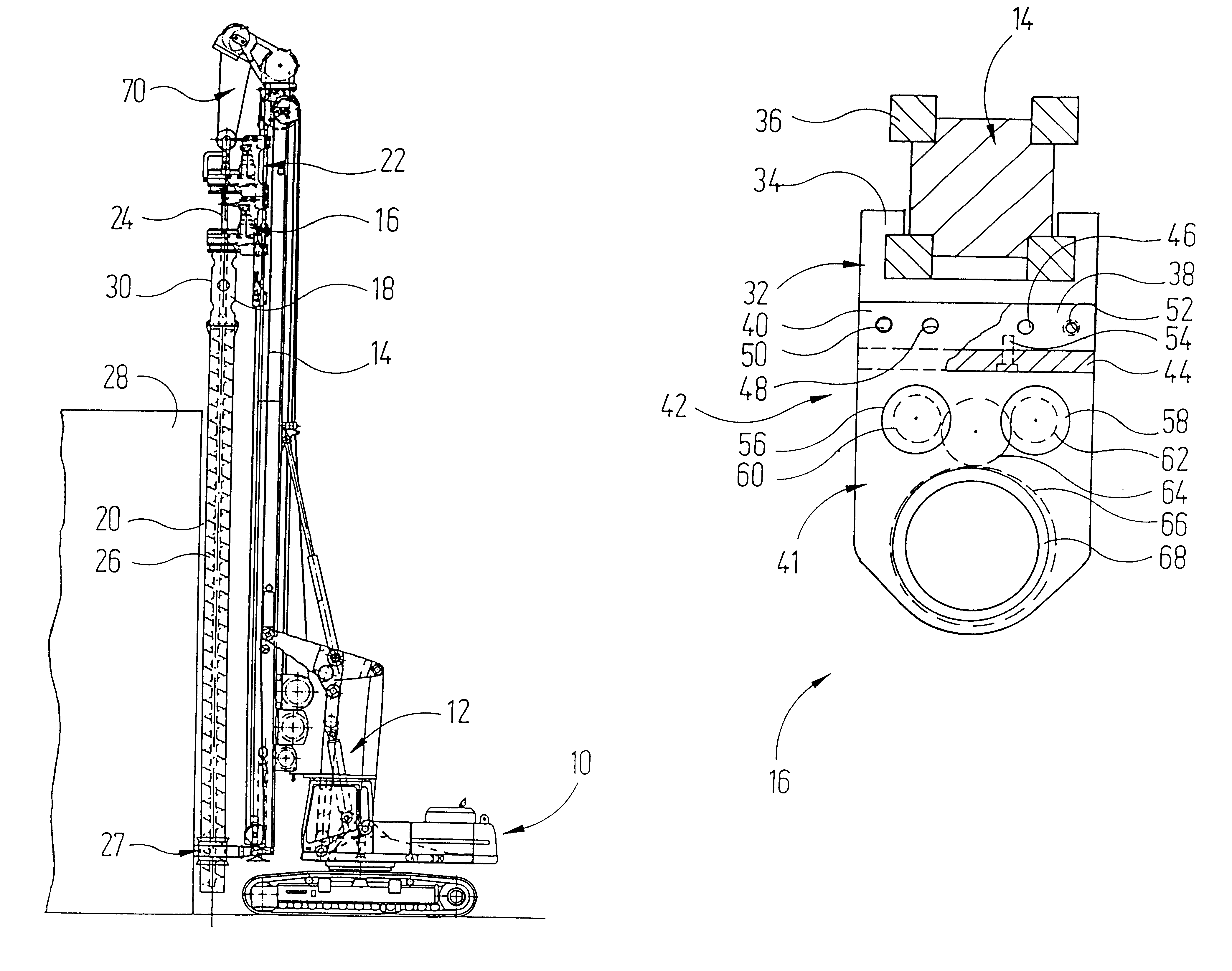
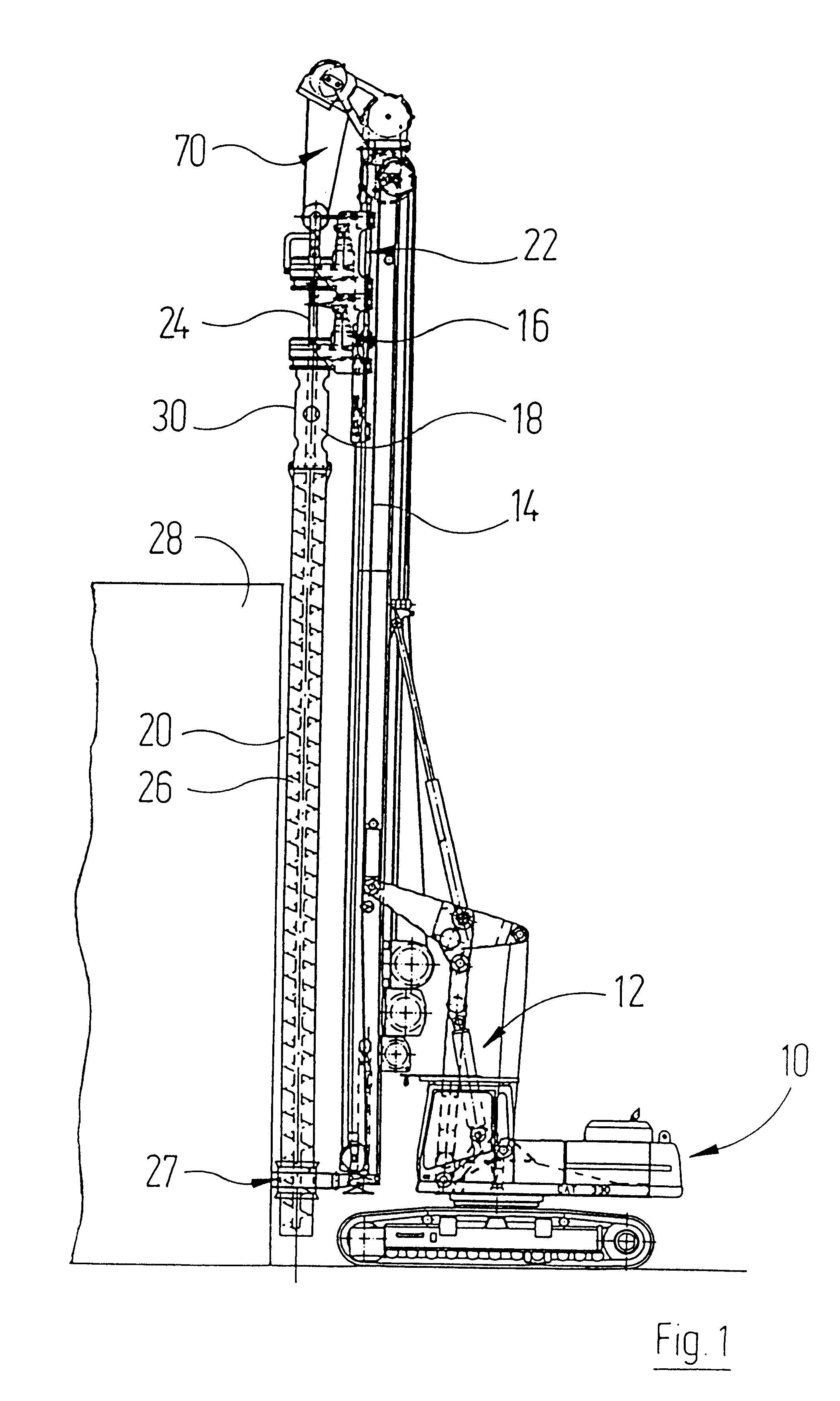
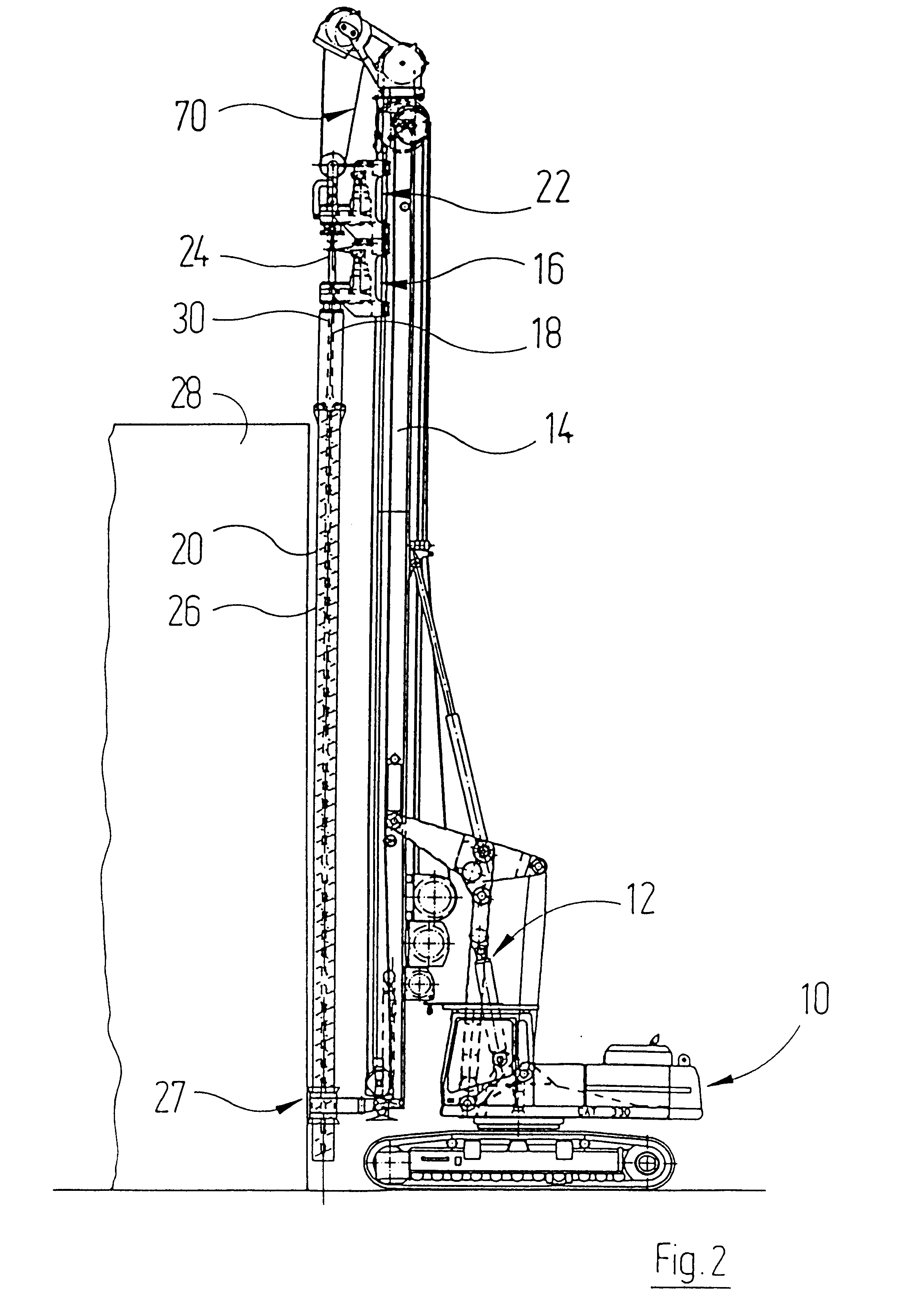
In FIG. 1, the reference 10 designates an excavator chassis in its entirety. The latter supports a fault finder 14, which is adjustable via a steering arrangement indicated in its entirety by the reference 12.

A drive carriage 16, which operates via a drive pipe 18 on a drill pipe 20, is displaceable in the vertical direction on the fault finder 14.

Lying above the drive carriage 16, a further drive carriage 22, which operates on a drive rod 24, is displaceable on the fault finder 14. The drive rod 24 supports a drill 26, which extends through the drill pipe 20.

Provided at the lower end of the fault finder is a pipe guide head 27, which forms a radial bearing for the drill pipe 20.

In order to produce a drill hole in the immediate vicinity of a schematically indicated building 28, the drill 26 is rotated and forced into the soil. According to the advance of the drill 26, the drill pipe 20 is also forced with rotation into the soil. The drill 26 constantly conveys the loosened soil upwa...


PUM


Abstract

A double-head drilling machine is disclosed, which by changing over or converting small component units can cooperate with drill or drill pipes of different diameters. To this end, drive carriages (16) operating on drills or drill pipes, for example, comprise a carriage base element (32), to which a drive unit (42) is releasably fitted. The drive unit (42) can thus be replaced by a different drive unit having essentially the same geometry, which is designed for operating with a drill or drill pipe having a different diameter.

Description

CROSS-REFERENCES TO RELATED APPLICATIONSNot applicable.Not applicable.1. Field of the InventionThe invention relates to a drilling machine according to the preamble of claim 1.Known drilling machines of this type are designed for working with drills or drill pipes having a given diameter and are used successfully in large numbers in order to produce pile foundations for buildings.2. Discussion of Relevant Art IncludingInformation Disclosed under 37 CFR 1.97-1.99.For new buildings in already built-up areas of a locality, it has already been proposed (DE 195 12 109 A1) to construct the drive carriages on the drill or drill pipe so that they are particularly radially compact in the vicinity of their free end, so that a drill hole can be formed in the immediate vicinity of an existing building wall.It would also be possible to make do with piles having reduced diameters in the immediate vicinity of already existing buildings for some applications in which it is unnecessary to provide a ...

Claims


Application Information

Patent Timeline
Patent Type & Authority Patents(United States)
IPC IPC(8): E21B17/00E21B7/00E21B17/22E21B10/00E21B10/44
CPCE21B7/005E21B17/22E21B10/44
Inventor SCHEID, WINFREIDHEINZ, NIKODEMUS
Owner DELMAG MASCHFAB REINHOLD DORNFELD
Why Eureka
Try Eureka