Safety running system for vehicle

a running system and vehicle technology, applied in the direction of braking systems, pedestrian/occupant safety arrangements, instruments, etc., can solve the problems of unnecessary collision avoidance control, risk of the driver feeling a physical disorder, and the subject vehicle with an oncoming vehicle ao is erroneously judged

Inactive Publication Date: 2001-07-31
HONDA MOTOR CO LTD
View PDF7 Cites 333 Cited by
  • Summary
  • Abstract
  • Description
  • Claims
  • Application Information

AI Technical Summary

Problems solved by technology

Due to this, with the safety running system described in FIG. 3, there is caused a problem that a possible collision of the subject vehicle with an oncoming vehicle Ao is erroneously judged as occurring as soon as the steering wheel of the subject vehicle is steered rightward even when in reality there is no such collision possibility.
As a result of this, a judgement is made that there is a collision possibility when in reality there is no such collision possibility, this triggering the performance of an unnecessary collision avoidance control, thereby causing a risk of the driver feeling a physical disorder.
Due to this, for instance in a case where the subject vehicle is steered so as to avoid an obstacle on the road side, an erroneous judgement of a collision possibility is made only when the azimuth of the travelling subject vehicle is temporarily directed to the side of the adjacent lane for opposite traffic, and therefore there is caused a problem that every time such an erroneous judgement is made, an unnecessary collision avoidance control is performed to make the driver feel troublesome.

Method used


Image

  • Safety running system for vehicle
  • Safety running system for vehicle
  • Safety running system for vehicle

Examples


first embodiment

[First Embodiment]

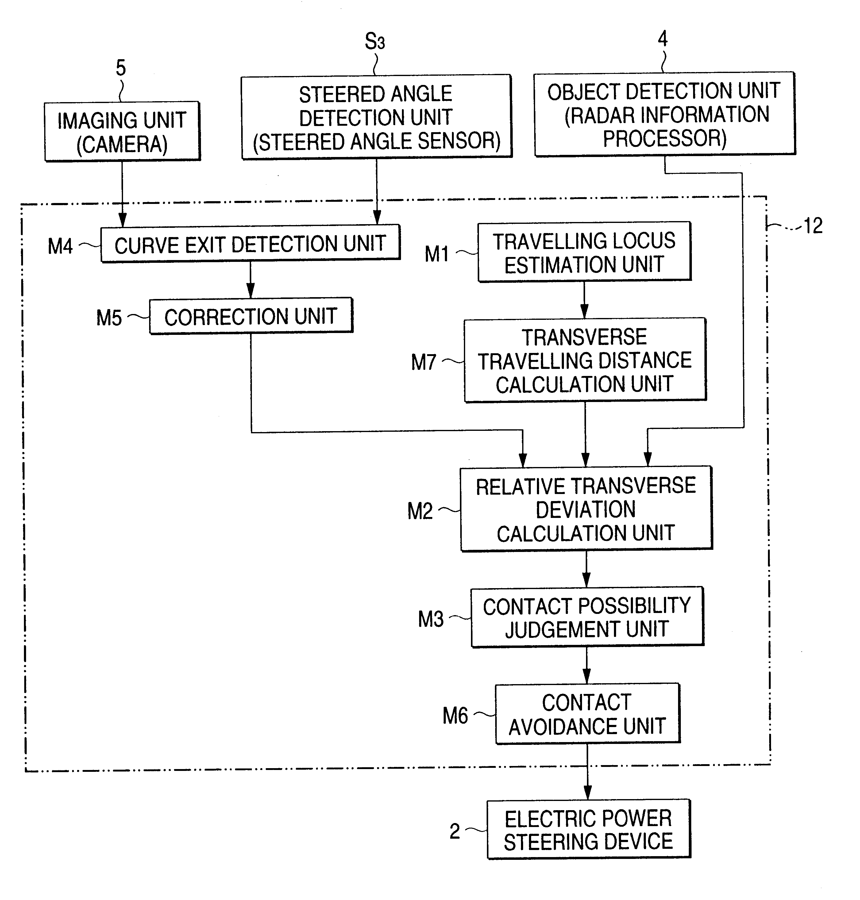
A first embodiment of the present invention, which prevents the occurrence of an erroneous judgement that is a collision possibility between the subject vehicle and an oncoming vehicle when the subject vehicle approaches an exit of a curve or bend will be described below with reference to the accompanying drawings.

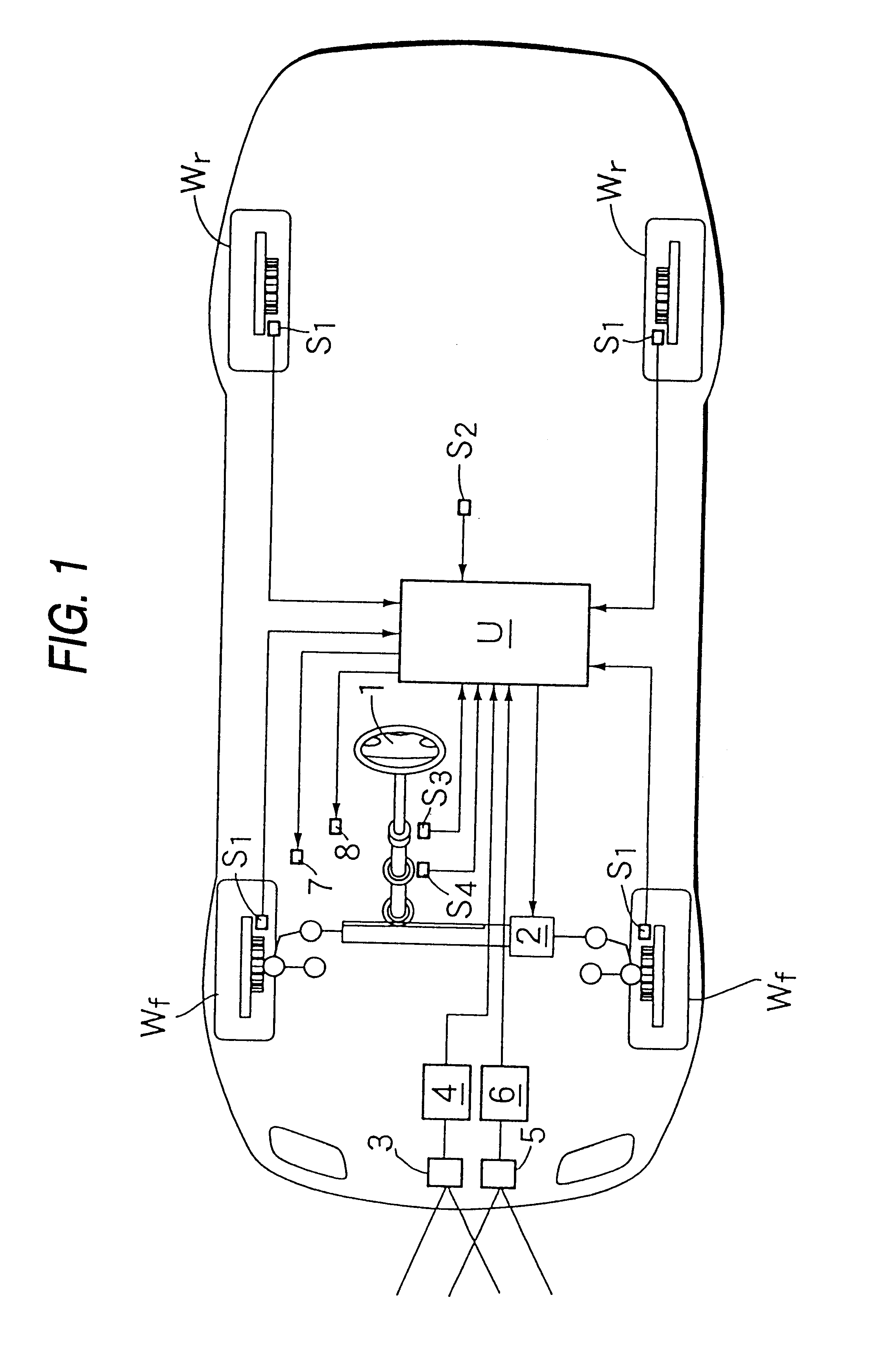
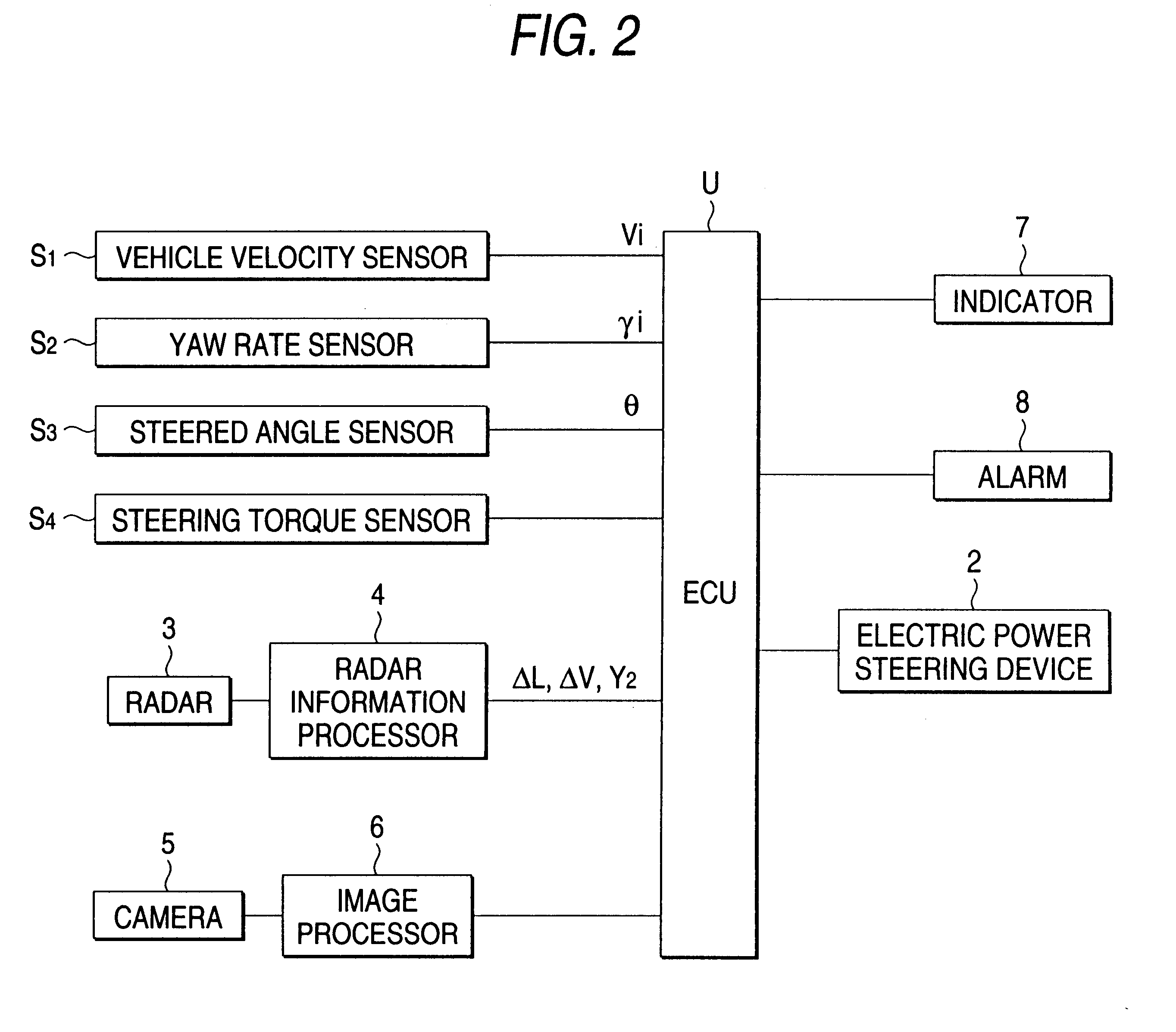
FIGS. 1 to 8 show the first embodiment of the present invention. As shown in FIGS. 1 and 2, a vehicle fitted with front left and right wheels Wf, Wf and rear left and right wheels Wr, Wr includes a steering handle or wheel 1 for steering the front left and right wheels Wf, Wf and an electric power steering device 2 for generating a steering force for assisting the driver in operating the steering wheel 1 and avoiding a collision. An electronic control unit U for controlling the operation of the electronic power steering device 2 receives signals input from a radar information processor 4 connected to a radar 3, an image processor 6 connected to a camera 5...

second embodiment

[Second Embodiment]

A second embodiment of the present invention, which prevents the occurrence of a collision avoidance operation based on an erroneous judgement of a possible collision between the subject vehicle and an oncoming vehicle when the driver of the subject vehicle tries to overtake a preceding vehicle will be described with reference to FIGS. 3, 4 and 9-14. Portions represented by the same reference numeral as the first embodiment are identical to those of the first embodiment, and the descriptions of them are omitted.

FIGS. 9 and 10 show an overall structural view of a vehicle provided with a safety running system of the second embodiment of the present invention, and a block diagram of the safety running, respectively. The vehicle shown in FIGS. 9 and 10 has the same equipment as that of the first embodiment except for the camera 5 and the image processor 6. Of course, the vehicle shown in FIGS. 1 and 2 can be applied to the second embodiment.

In addition, the electronic...

third embodiment

[Third Embodiment]

A third embodiment of the present invention, which prevents the performance of an unnecessary collision avoidance control by making a judgement of a possible collision with an oncoming vehicle in an accurate fashion will be described with reference of FIGS. 3, 4 and 15-23. Portions represented by the same reference numeral as the first embodiment are identical to those of the first embodiment, and the descriptions of them are omitted.

FIGS. 15 and 16 show an overall structural view of a vehicle provided with a safety running system of the second embodiment of the present invention, and a block diagram of the safety running, respectively. The vehicle shown in FIGS. 15 and 16 has the same equipment as that of the first embodiment except for the steered angle sensor S3. Of course, the vehicle shown in FIGS. 1 and 2 can be applied to the third embodiment. In this embodiment, the image processor 6 calculates an angle .theta. formed by the center line of the road and the ...


PUM


Abstract

In a safety running system, a transverse travelling distance resulting when a subject vehicle travels to a current position of an oncoming vehicle is calculated based on the vehicle velocity and yaw rate of the subject vehicle, a relative transverse distance of the oncoming vehicle relative to a vehicle body axis of the subject vehicle is calculated based on a relative distance, relative velocity and relative angle between the subject vehicle and the oncoming vehicle detected by a radar information processor. When a relative transverse deviation obtained by subtracting the transverse travelling distance from the relative transverse distance resides within a range and that state continues to exist over a predetermined time period, it is judged that there is a collision possibility of the subject vehicle with the oncoming vehicle, and automatic steering is performed so as to avoid a collision.

Description

1. Field of the InventionThe present invention relates to a safety running system for a vehicle for preventing a subject vehicle from coming into contact with an oncoming vehicle on an adjacent lane of the road for opposite traffic by using an object detection unit such as a radar device.2. Description of the Related ArtA safety running system for a vehicle as described above is well known in the official gazette of Japanese Patent Unexamined Publication (Kokai) No. HEI 7-14100.The safety running system disclosed in the above official gazette is adapted to avoid a collision of a subject vehicle with an oncoming vehicle on an adjacent lane of the road for opposite traffic by generating an alarm to the driver of the subject vehicle to make the driver perform a voluntary collision avoidance operation or automatically applying the brakes of the subject vehicle in the event that the subject vehicle enters the adjacent lane for opposite traffic to thereby encounter a possible collision wi...

Claims


Application Information

Patent Timeline
Patent Type & Authority Patents(United States)
IPC IPC(8): B62D1/28B62D1/00G01S13/00G01S13/93G01S13/86G01S13/931
CPCB62D15/0265G01S13/931G01S13/867G01S2013/9342G01S2013/9375G01S2013/9357G01S2013/9353G01S2013/9322G01S2013/9318G01S2013/93271G01S2013/932
Inventor KODAKA, KENJISHINMURA, TOMOYUKISUGIMOTO, YOICHI
Owner HONDA MOTOR CO LTD
Why Eureka
Try Eureka