
Dead reckoning routing of packet data within a network of nodes having generally regular topology

a network and topology technology, applied in data switching networks, instruments, digital computer details, etc., can solve the problems of increasing the length of the queue, becoming a very severe constraint, and more difficult to satisfy the stability criterion

Inactive Publication Date: 2001-08-07
PATENTPORTFOLIO 2 S A R L
View PDF17 Cites 89 Cited by
  • Summary
  • Abstract
  • Description
  • Claims
  • Application Information

AI Technical Summary

Benefits of technology

Although the method provides particular advantages in optical networks, especially where photonic devices are used, it is by no means limited to use with such networks. It also gives advantages when used, for example, with high-speed electronic networks, or with optical networks using electronic switching logic.

Problems solved by technology

If this condition is not observed the system becomes unstable since the ratio of the packet arrival rate to the service rate at a node can become greater than 1, so that queue lengths can grow indefinitely.
For high transmission speeds, or for short packet lengths, this stability criterion is more difficult to satisfy.
It becomes a very severe constraint in the case of ultra-high speed networks operating at multi-Gbit / s transmission rates, particularly when the transmission format uses fixed-length packets or cells of at most a few tens of bytes in length.
Photonic logic devices are much less developed than electronic ones, they have primitive functionality and are relatively poorly integrated, power hungry and costly and are unlikely to achieve a comparable level of development for many years to come.
This has the disadvantage that the address has to be read, processed and modified at every node.
This imposes a significant overhead of complex bit-level processing.
Also, since this approach does not allow for deflection from the predetermined path, deflection routing cannot be used.
Again, this amount of bit-level processing is a significant disadvantage in the context of the system intended to operate at high bit rates.
Although the paper makes reference to the possibility of deflection routing, the routing scheme, because of its deterministic nature, is not well adapted for such an approach.
However, unlike random routing which is typically very inefficient, dead reckoning can provide good routing efficiency and network performance.

Method used


Image

  • Dead reckoning routing of packet data within a network of nodes having generally regular topology
  • Dead reckoning routing of packet data within a network of nodes having generally regular topology
  • Dead reckoning routing of packet data within a network of nodes having generally regular topology

Examples


Embodiment Construction

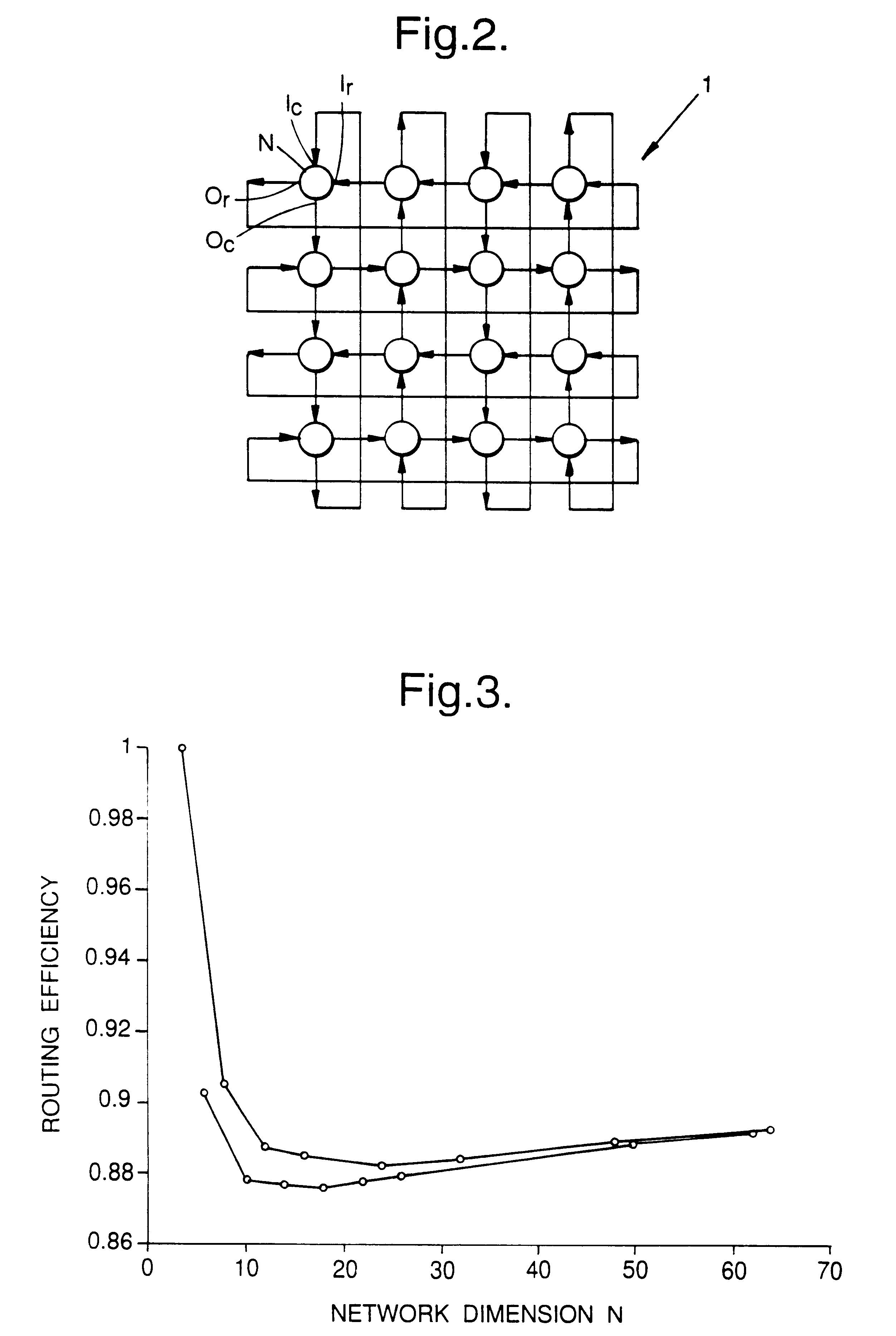
As shown in FIG. 2, one example an optical network 1 in accordance with this invention comprises a plurality of nodes N interconnected in a regular mesh pattern. In the example shown in FIG. 2, a Manhattan Street Network (MS-Net) topology is used. This is a two-connected, regular network with unidirectional links. There is an even number of rows and columns with two links arriving and two links leaving each node N. Logically, the links form a grid on the surface of a torus, with links in adjacent rows or columns travelling in opposite directions. FIG. 2 shows a 16-node (4.times.4) MS-Net.

FIG. 4 shows the structure of an individual node N. It incorporates a switch 2 which is set to route an incoming packet either to the node's row output O.sub.r, to the column output O.sub.c or to the host local to the node. This host may, for example, be one of a number of processors connected to respective nodes and forming in combination a multi-processor parallel processing computer system. The s...


PUM


Abstract

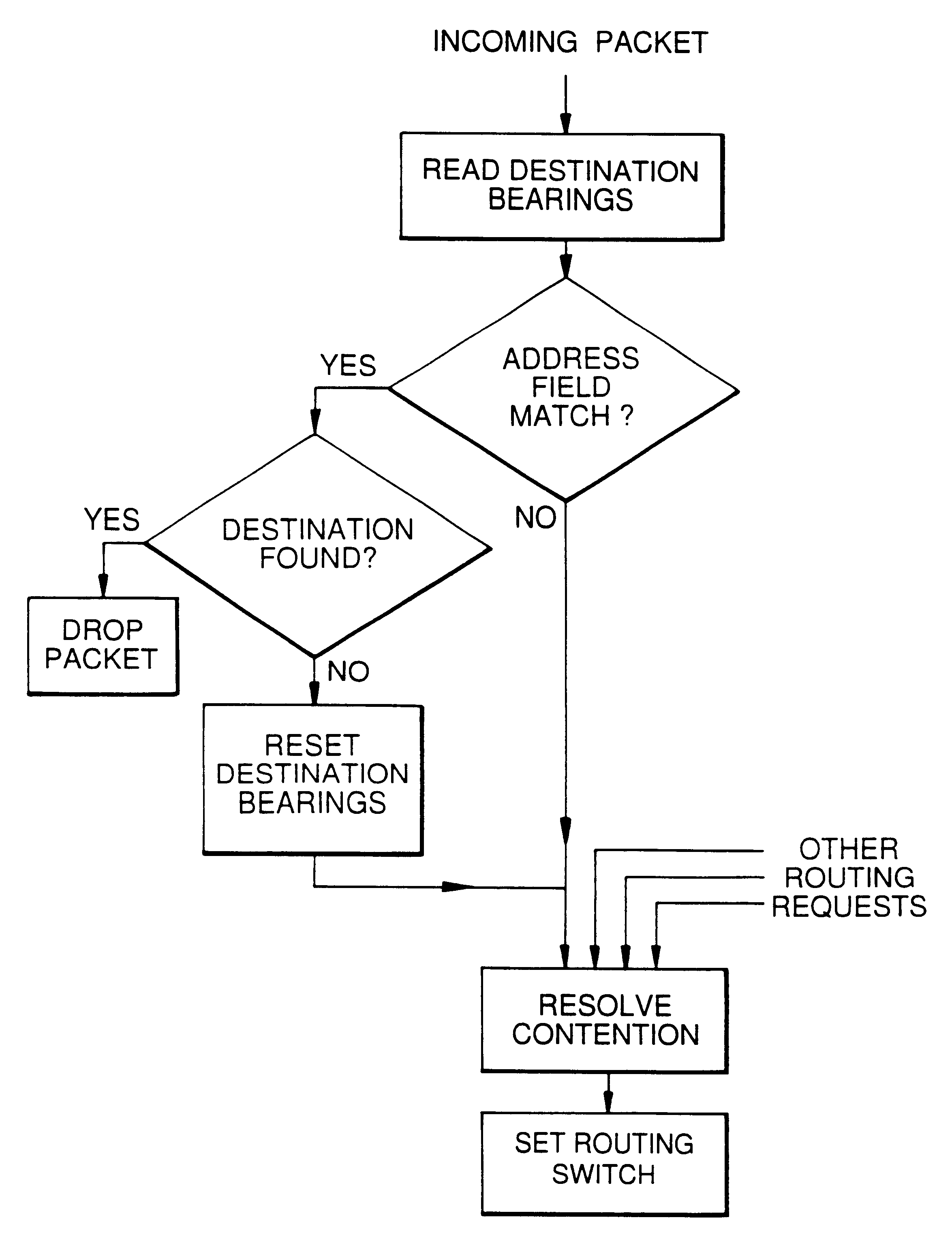
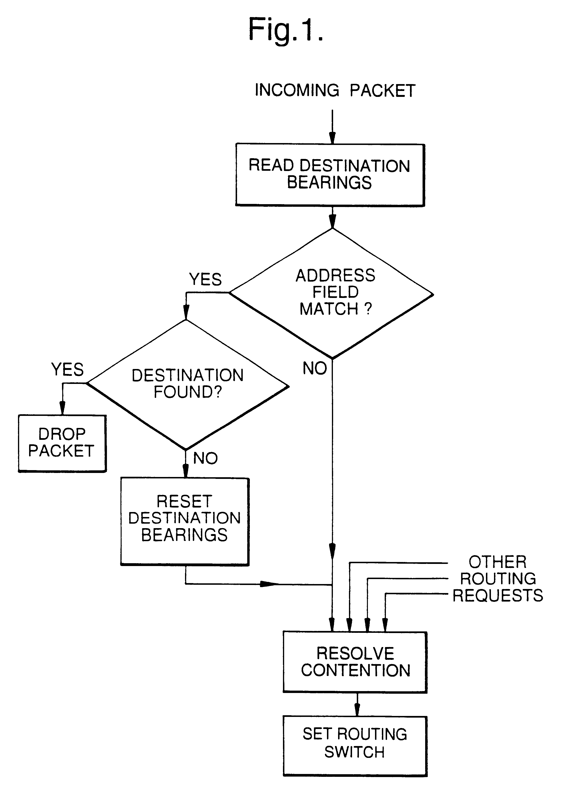
A packet is routed by "dead reckoning" on a network having a generally regular topology. The packet is received at a node where a local routing decision is made. The packet is output in a direction selected according to the routing decision. The packet carries in addition to a destination address a directional flag indicating explicitly the preferred direction of onward travel and the routing decision is made using this flag. Several flags may be used, corresponding to different dimensions of the network.

Description

BACKGROUND TO THE INVENTION1. Field of the InventionThe present invention relates to a method of routing packets on a network, and to networks and nodes adapted to implement the method.2. Related ArtPacket routing networks may be used, for example, to interconnect the different processors of a multi-processor computer, or as the basis of a LAN interconnecting a number of different computers. In the future, it is envisaged that such networks might be used for distributed processing applications such as the provision of shared virtual-reality environments--"virtual meeting places"--or for fast complex visualisation of data, for example in financial institutions. Such a network might also be used for the internal architecture of a packet switch used, for example, in a telecommunications network.All the examples discussed above will benefit from networks capable of operating at ultrafast speeds, e.g 10 GBit / s or more. To achieve such speeds, it is essential that there is efficient routi...

Claims


Application Information

Patent Timeline
Patent Type & Authority Patents(United States)
IPC IPC(8): H04L12/56H04Q11/00H04B10/27H04L12/721
CPCH04L45/06H04L45/34H04Q11/0062H04Q2011/009H04Q11/0066H04Q2011/0041
Inventor COTTER, DAVIDTATHAM, MARTIN C
Owner PATENTPORTFOLIO 2 S A R L
Learn More