Separation of data and control in a switching device

a switching device and data control technology, applied in data switching networks, instruments, digital computer details, etc., can solve the problems of inefficiency of conventional routers in a number of respects, design trade-offs (costs), and inability to connect in the switch, so as to reduce the occurrence of dropping packets, reduce the size of the output buffer, and reduce the effect of dropping packets

Inactive Publication Date: 2005-07-12
JUMIPER NETWORKS INC
View PDF10 Cites 52 Cited by
  • Summary
  • Abstract
  • Description
  • Claims
  • Application Information

AI Technical Summary

Benefits of technology

[0009]To minimize the occurrence of dropping packets, designers developed non head-of-line blocking routers. Referring now to FIG. 1B, a conventional non head-of-line blocking router includes a plurality of input ports 2 each including an input buffer (memory) 4, a switching device 6 and a plurality of output ports 8 each having an output buffer 9.

Problems solved by technology

Blocking refers to a condition in which a connection cannot be made in the switch due to the unavailability of the desired output port (the port is busy, e.g., routing another packet from a different input port).
Unfortunately, conventional routers are inefficient in a number of respects.
However, design trade-offs (cost) often necessitate smaller buffers for each port.
With the smaller buffers, the possibility arises for packets to be dropped due to b

Method used


Image

  • Separation of data and control in a switching device
  • Separation of data and control in a switching device
  • Separation of data and control in a switching device

Examples


Embodiment Construction

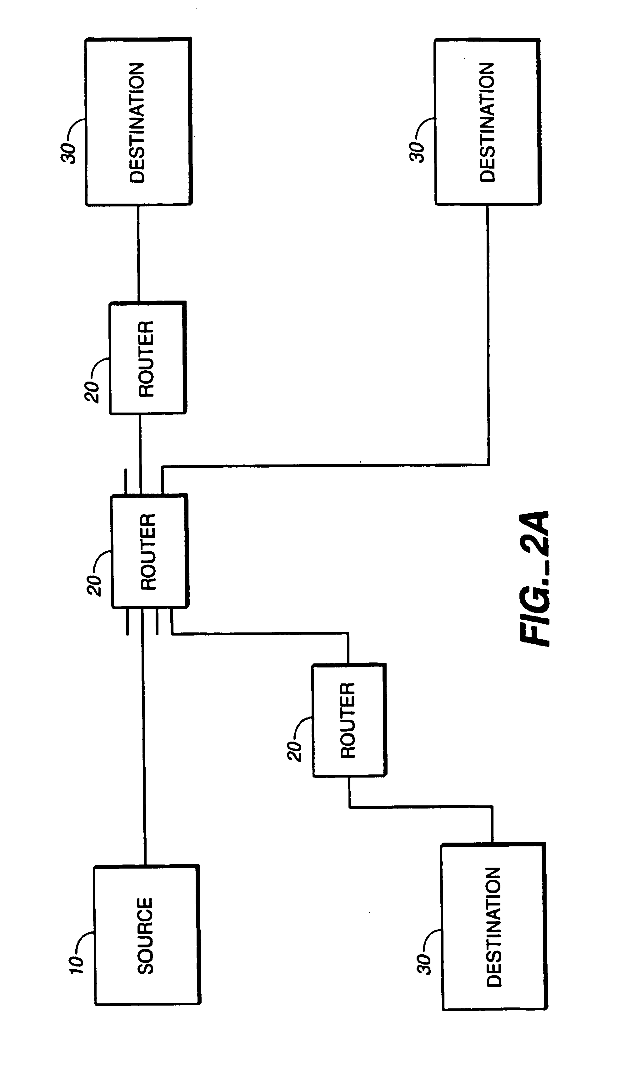
[0065]Referring to FIG. 2A, in a packet switching system, a source 10 is connected to one or more routers 20 for transmitting packets to one or more destinations 30. Each router includes a plurality of multi-function multiports that are connected to various sources and destinations. A packet from source 10 may pass through more than one router 20 prior to arriving at its destination.

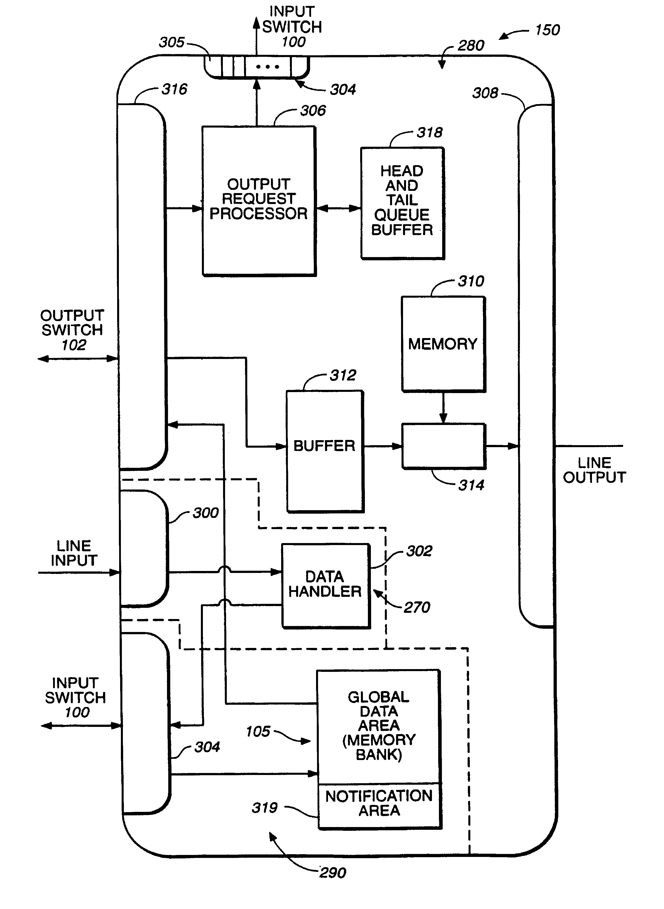
[0066]Referring to FIG. 2B, each router 20 includes an input switch 100, an output switch 102, a global data buffer 104 including one or more memory banks 105, a controller 106 and a plurality of multi-function multiports 150 (150-0 through 150-3), respectively. Associated with the controller 106 is controller memory 109 for storing a routing table. Input switch 100 and output switch 102 are connected to each multi-function multiport 150 in router 20. In one embodiment, router 20 includes plug-and-play multi-function multiports which allows for easy expansion capability. The present invention will be des...


PUM


Abstract

A method and apparatus for switching a data packet between a source and destination in a network. The data packet includes a header portion and a data portion. The header portion includes routing information for the data packet. The method includes defining a data path in the router comprising a path through the router along which the data portion of the data packet travels and defining a control path comprising a path through the router along which routing information from the header portion travels. The method includes separating the data path and control path in the router such that the routing information can be separated from the data portion allowing for the separate processing of each in the router. The data portion can be stored in a global memory while routing decisions are made on the routing information in the control path.

Description

[0001]This is a continuation-in-part of U.S. application Ser. No. 08 / 901,061, entitled “MEMORY ORGANIZATION IN A SWITCHING DEVICE”, filed Jul. 24, 1997 now U.S. Pat. No. 6,493,347, which is a continuation-in-part of U.S. application Ser. No. 08 / 844,171, entitled “HIGH SPEED SWITCHING DEVICE”, filed Apr. 18, 1997, now issued as U.S. Pat. No. 5,905,725, which is a continuation-in-part of U.S. application Ser. No. 08 / 767,576, entitled “HIGH SPEED VARIABLE LENGTH BEST MATCH LOOK-UP IN A SWITCHING DEVICE”, filed on Dec. 16, 1996, now issued as U.S. Pat. No. 5,909,440.BACKGROUND[0002]The present invention relates generally to data routing systems, and more particularly to methods and apparatus for efficiently routing packets through a network.[0003]In packet switched communication systems, a router is a switching device which receives packets containing data or control information on one port, and based on destination information contained within the packet, routes the packet out another ...

Claims


Application Information

Patent Timeline
IPC IPC(8): H04Q11/04H04L12/56H04L12/46H04L49/111H04L49/901
CPCH04L12/56H04L12/5601H04L29/06H04L45/00H04L45/7457H04L47/6225H04L49/108H04L49/1538H04L49/203H04L49/25H04L49/3072H04L49/3081H04L49/608H04L49/90H04L49/901H04L49/9042H04L49/9047H04L49/9057H04Q11/0478H04L45/72G06F15/167H04L49/103H04L49/252H04L2012/5652H04L2012/5679H04L2012/5681H04L69/22H04L45/74591H04L9/40
Inventor SINDHU, PRADEEP S.KOMPELLA, KIREETIFERGUSON, DENNIS C.LIENCRES, BJORN O.AGARWAL, NALINIJU, HANN-HWANLIM, RAYMOND MARCELINO MANESEOSKOUY, RASOUL MIRZAZADEHVEERAGANDHAM, SREERAM
Owner JUMIPER NETWORKS INC
Why Eureka
Try Eureka