Carriers and polishing apparatus

a technology of air pressure and polishing equipment, which is applied in the direction of grinding drives, manufacturing tools, lapping machines, etc., can solve the problems of prone to damage during polishing work, extreme poor mass production,

Inactive Publication Date: 2001-08-14
SPEEDFAM CO LTD
View PDF5 Cites 56 Cited by
  • Summary
  • Abstract
  • Description
  • Claims
  • Application Information

AI Technical Summary

Problems solved by technology

In the carrier of the above related art, however, there were the following problems.
Therefore, in a carrier 100 of the related art having a retainer ring 104 set to such a thickness and formed by a soft material such as EG, the number of polishable wafers W produced within the desired range was about 200 sheets, which was extremely poor in terms of mass production.
While a retainer ring 104 made of a hard material, however, is superior in wear resistance, it is liable to be damaged during polishing work by the outer edge of the wafer W striking the inner peripheral surface of the retainer ring 104.

Method used


Image

  • Carriers and polishing apparatus
  • Carriers and polishing apparatus
  • Carriers and polishing apparatus

Examples


first embodiment

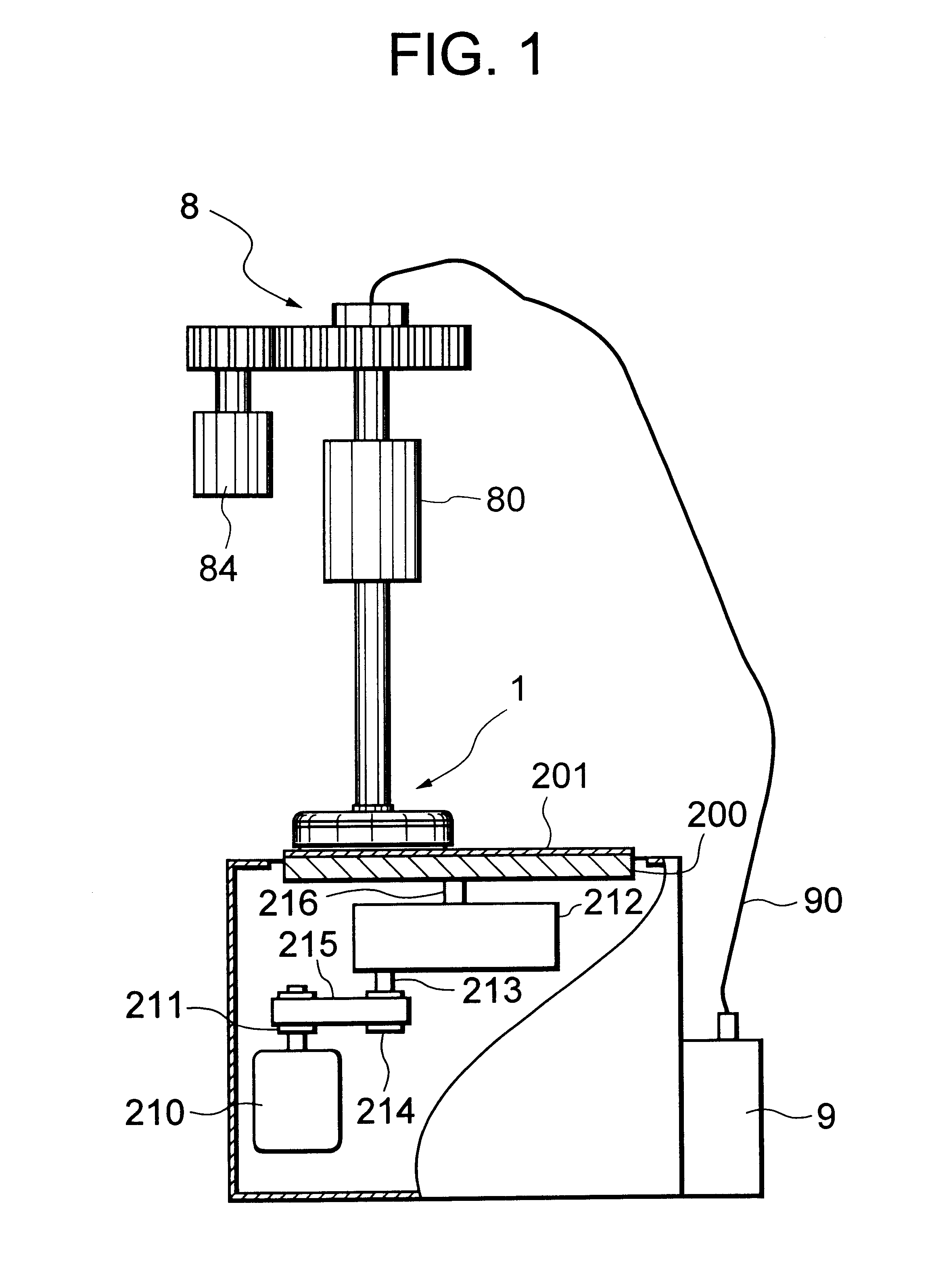
FIG. 1 is a partially cut away front view of a polishing apparatus according to the present invention.

As shown in FIG. 1, the polishing apparatus is provided with a lower platen 200 having a polishing pad 201 attached to its front surface, a carrier 1, a rotary drive mechanism 8 serving as the rotary drive means, and an air pump 9 serving as a fluid feed means.

The lower platen 200 is designed to be driven to rotate by a main motor 210 inside the apparatus housing.

A belt 215 is wound around a pulley 211 attached to the main motor 210 and a pulley 214 attached to an input shaft 213 of a transmission 212. The lower platen 200 is attached to an output shaft 216 of the transmission 212.

Due to this, the rotation of the main motor 210 is transmitted to the pulley 214, the rotation of the pulley 214 is converted in speed by the transmission 212 and transmitted to the output shaft 216, and the lower platen 200 is rotated at a predetermined speed.

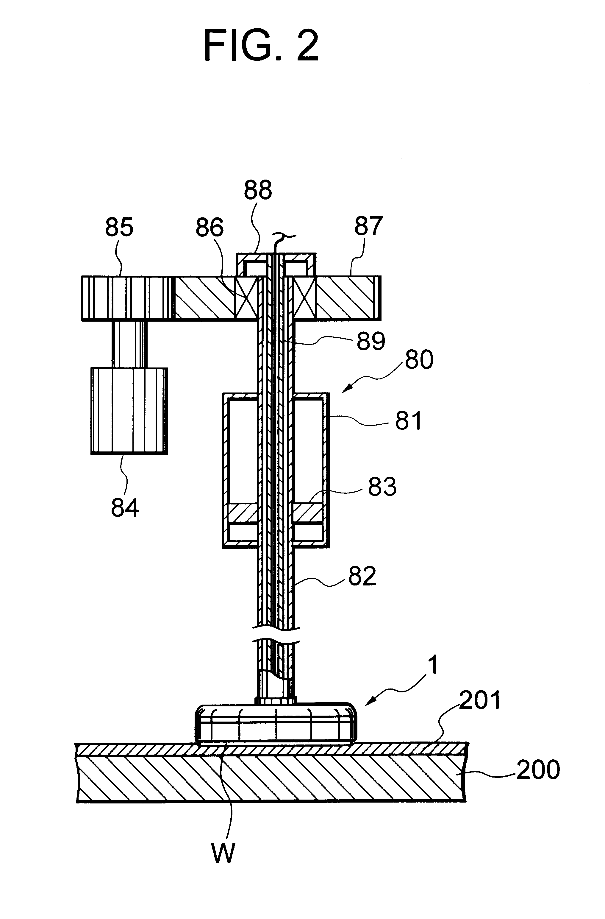
The rotary drive mechanism 8 is a mechanism fo...

second embodiment

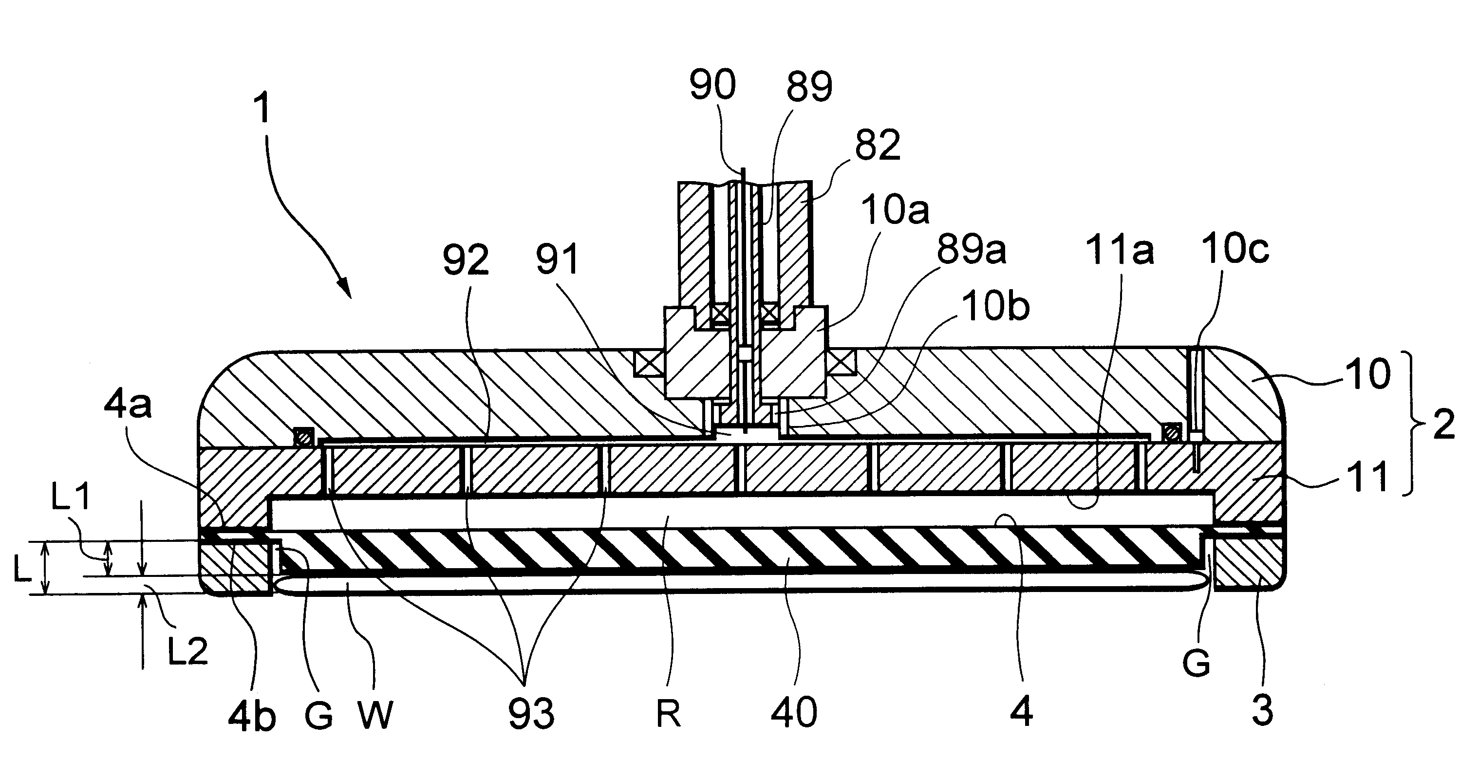
FIG. 8 is a sectional view of a carrier, which is an essential portion of a polishing apparatus according to a second embodiment of the present invention.

The carrier 1 of this embodiment differs from that of the first embodiment of the invention in the structure of the margin block.

The margin block 40 in the carrier 1 of the first embodiment of the invention is solid, so the margin block 40 becomes too thick and hard and it is no longer possible to maintain the front side reference of the wafer W. Therefore, it is not possible to make the margin block 40 too thick.

In this embodiment of the invention, instead of the solid margin block 40, a hollow margin block 40' is provided projecting out from the bottom surface of the sheet 4'. Specifically, the thickness of the bottom surface 40a' of the margin block 40' and the thickness of the side surface 40b' are set to become substantially equal to the thickness of the sheet 4. The sheet 4' is formed with a plurality of holes 4c' for communi...


PUM


Abstract

A carrier and a polishing apparatus are designed to improve the mass producibility of wafers while using a retainer ring formed by a soft material. A rubber sheet 4 is bonded to the bottom surface of a carrier body 2 of the carrier 1 to define a pressure chamber R, a retainer ring 13 formed by a soft material such as EG is bonded to the bottom surface of the sheet 4. A margin block 40 is provided projecting out from the bottom side of the sheet 4, and the thickness of the retainer ring 13 is set to be substantially equal to the sum of the thickness L1 of the margin block 40 and the thickness L2 of the wafer W.

Description

1. Field of the InventionThe present invention relates to an air pressure type carrier and polishing apparatus provided with a soft retainer ring.2. Description of the Related ArtIn general, polishing a wafer by front side reference gives a higher polishing accuracy than polishing by back side reference, so most carriers adopt an air pressure type structure.FIG. 13 is a sectional view of an example of an air pressure type carrier of the related art.A carrier 100 is formed with a depression 101 at its bottom surface. This depression 101 is covered with a sheet 102 to define a pressure chamber R. An air feed path 103 communicating with the pressure chamber R is provided at the center of the carrier 100. A retainer ring 104 for holding the wafer W is attached at the outer periphery of the bottom surface of the carrier 100 by an adhesive (not shown).Due to this configuration, the carrier 100 can be made to rotate in a state with a wafer W brought into contact with the top of a polishing...

Claims


Application Information

Patent Timeline
Patent Type & Authority Patents(United States)
IPC IPC(8): B24B37/04H01L21/304B24B37/30B24B37/32
CPCB24B37/32B24B37/30H01L21/304
Inventor WANG, XU-JINIZUMI, SHIGETOSUGIYAMA, MISUOTANAKA, HIDEO
Owner SPEEDFAM CO LTD
Why Eureka
Try Eureka