All purpose FLIR kit for aircraft

a kit and aircraft technology, applied in the field of forward-looking infrared (flir) imaging system, can solve the problems of not meeting the commonality and other requirements of the second generation flir

Inactive Publication Date: 2001-08-14
UNITED STATES OF AMERICA THE AS REPRESENTED BY THE SEC OF THE ARMY
View PDF10 Cites 23 Cited by
  • Summary
  • Abstract
  • Description
  • Claims
  • Application Information

AI Technical Summary

Problems solved by technology

The Apache and the current U.S. Army Comanche prototype helicopter models include FLIR components which perform the tasks of lo

Method used


Image

  • All purpose FLIR kit for aircraft
  • All purpose FLIR kit for aircraft
  • All purpose FLIR kit for aircraft

Examples


Embodiment Construction

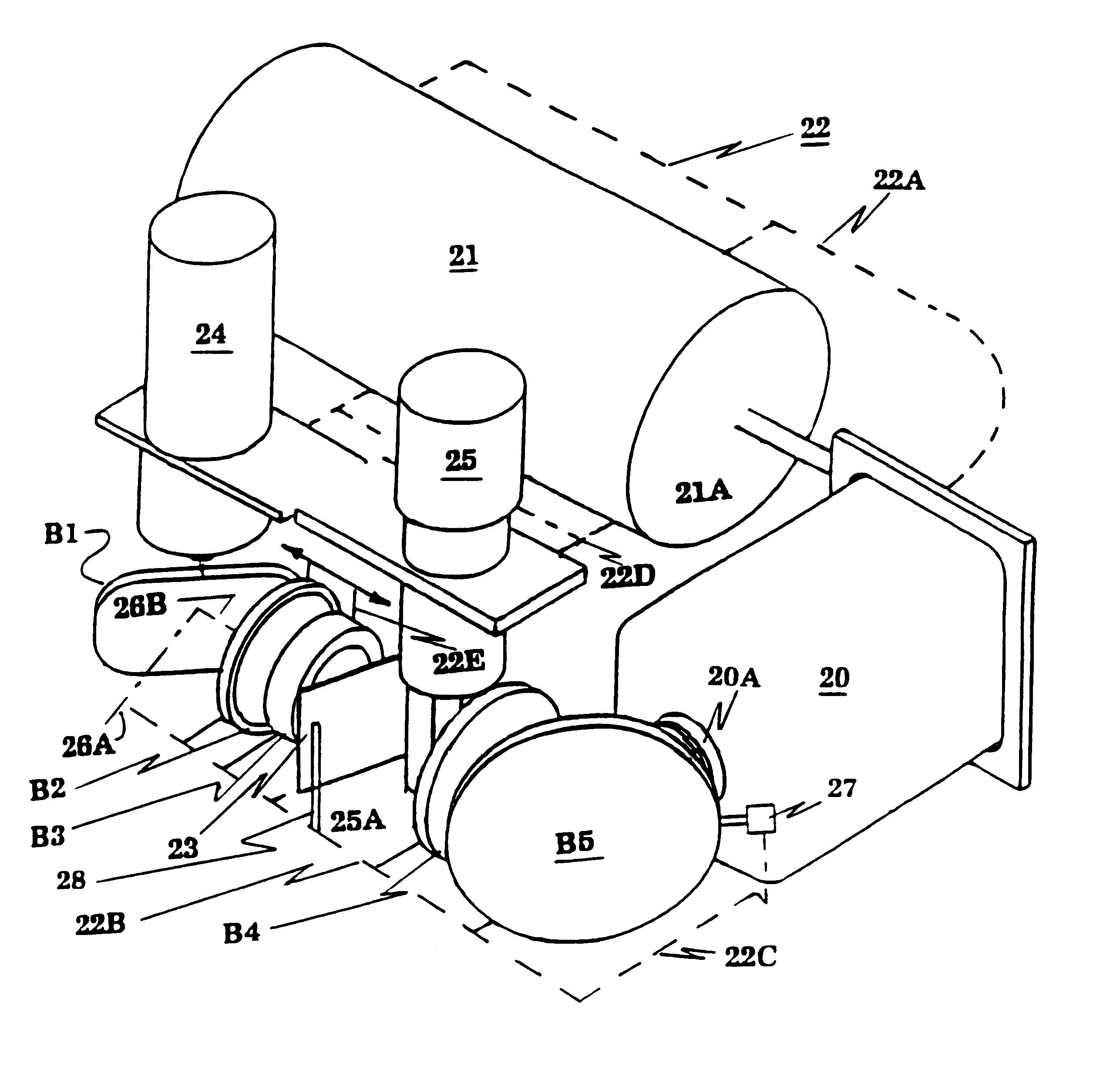
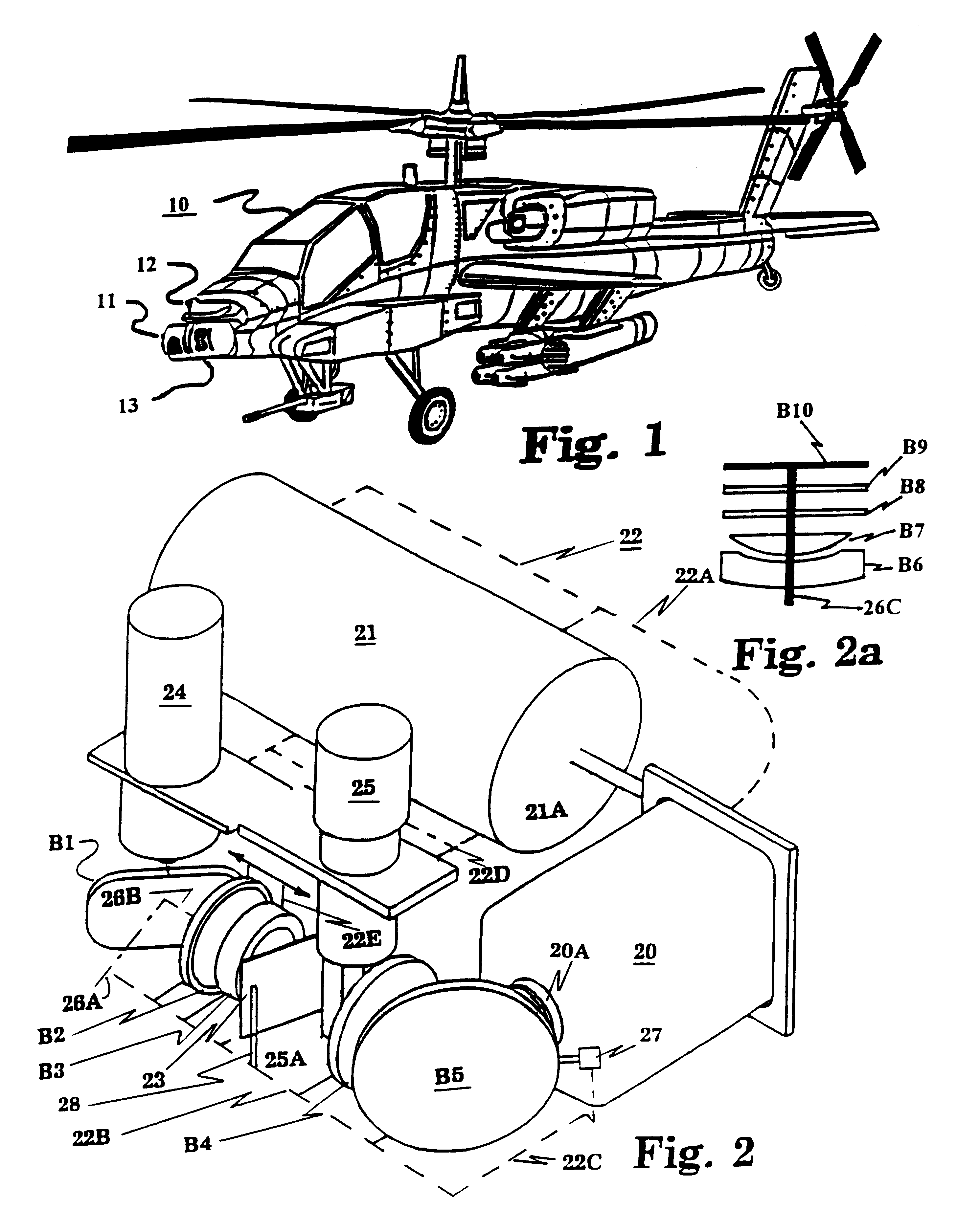
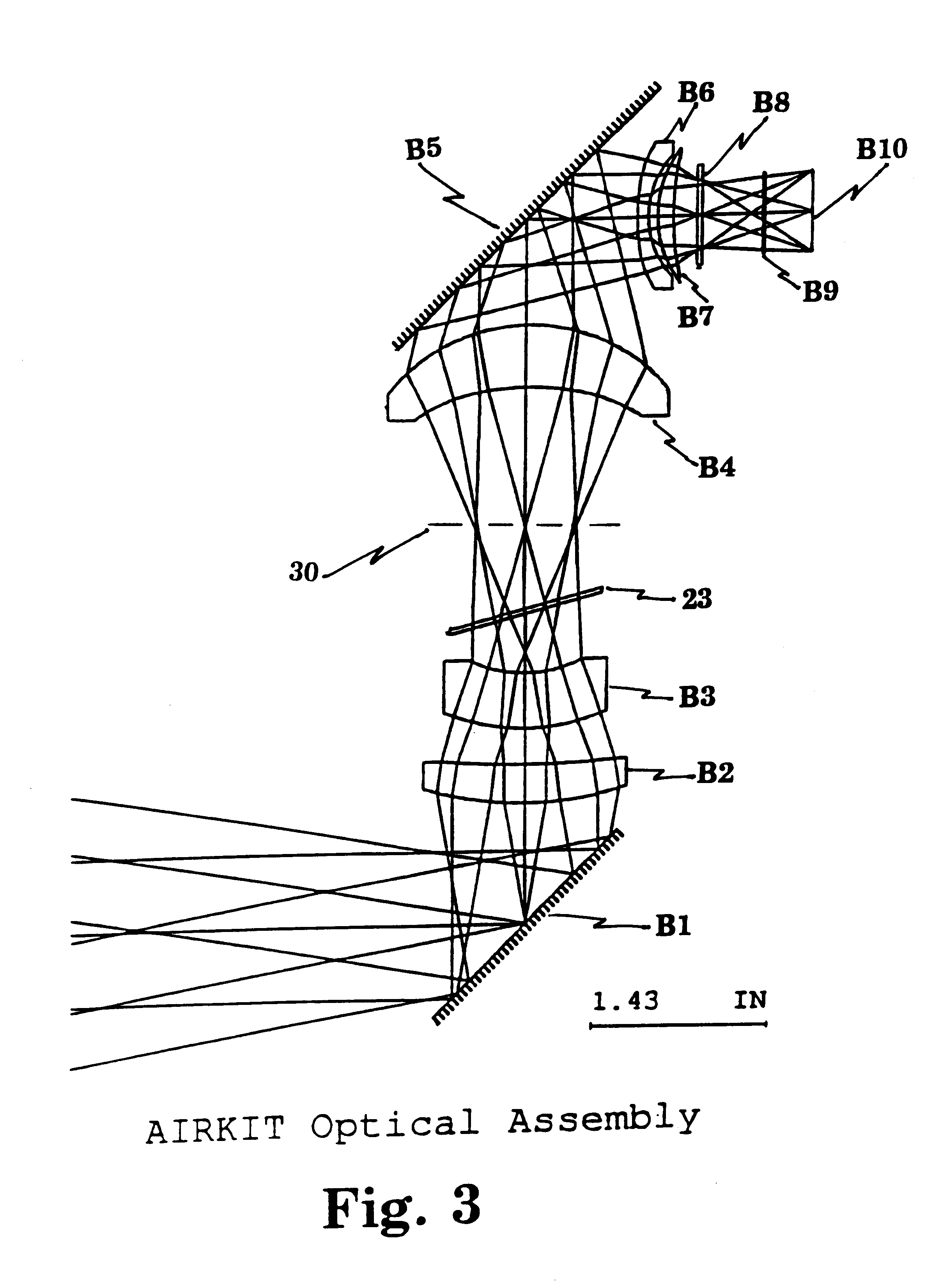
Referring now to the drawings, and more particularly to FIG. 1 there is shown an Army Apache type Helicopter equipped with separate night and day surveillance systems. The optics and many of the other supporting elements for these systems are housed in three turrets attached to the nose of the aircraft. On other aircraft it is proposed to locate these in other positions, but their form and function will remain the same. The first of the above turrets 10 contains a gunner's FLIR that supplies a high resolution visible image in both digital and analog formats to support manual or automatic target detection, recognition, classification, threat assessment, fire control and in emergencies to aid in navigation. A second turret 11 contains a navigation FLIR for the pilot that supplies a normal resolution flicker free visible image. The third turret contains daysights and observation equipment for use under high light level conditions FIG. 2 shows an isometric view of the components of appl...


PUM


Abstract

FLIR kits are provided comprising optical and related components which can be commonly used for both navigational and targeting scenarios. Such components include a common detector interface, imaging optics, scanner, interlacer, filter wheel, and thermal reference sources with integrated chopper/rotator assembly, all of which when assembled form a stand-alone imaging sensor when combined with a common associated electronics subassembly. The kits are integrated into standard navigational and targeting platforms of the type found on the AH-64 Apache and RAH-66 Comanche attack helicopters.

Description

1. Field of the InventionThe present invention generally relates to a Forward Looking InfraRed (FLIR) imaging system. More particularly it involves a multi-functional kit of core sensor components, including novel optical layouts, which can be integrated into a variety of configurations for varied uses, including target detection, acquisition, identification, classification, prioritization and disposal.2. Description of Prior ArtIn a prior art U.S. Pat. No. 5,479,016 entitled, "Compact Second Generation FLIR Kit", issued to J. Curry, et. al., on Dec. 26, 1995, there is described a FLIR "Kit" which replaces older First Generation FLIR's in common military ground vehicles. The kit is comprised of various modules, which may be upgraded and interchanged as long as the Kit interfaces to the host platform remain unchanged. This compact Kit is designed to meet the requirements for ground based targeting missions, and is optimized for integration within appropriate platforms. In a pending p...

Claims


Application Information

Patent Timeline
IPC IPC(8): G02B23/00G02B23/12
CPCG02B23/12
Inventor HALL, JOHN M.WRIGHT, RICHARD A.
Owner UNITED STATES OF AMERICA THE AS REPRESENTED BY THE SEC OF THE ARMY
Why Eureka
Try Eureka