Heated vascular occlusion coil development system

a development system and vascular occlusion technology, applied in the field of flexible delivery members, can solve the problems of stiff catheters, difficult to guide catheters through the vasculature of the body, and little control over the exact placement of coils

Inactive Publication Date: 2001-08-21
CODMAN & SHURTLEFF INC
View PDF39 Cites 165 Cited by
  • Summary
  • Abstract
  • Description
  • Claims
  • Application Information

AI Technical Summary

Problems solved by technology

With these placements systems there is very little control over the exact placement of the coil since the coil may be ejected to a position some distance beyond the end of the catheter.
One problem with this type of coil placement system which utilizes a pusher wire which extends through the entire length of the catheter and which is sufficiently stiff to push an attachment ball out of engagement with the socket at the distal end of the catheter is that the pusher wire inherently causes the catheter to be very stiff with the result that it is very difficult to guide the catheter through the vasculature of the body.
Such a system also suffers from the problem of having a separate, relatively stiff element which extends throughout the length of the catheter with resulting stiffness of the catheter.
Upon heating the heat responsive coupling member softens thereby reducing its yield strength.

Method used


Image

  • Heated vascular occlusion coil development system
  • Heated vascular occlusion coil development system
  • Heated vascular occlusion coil development system

Examples


Embodiment Construction

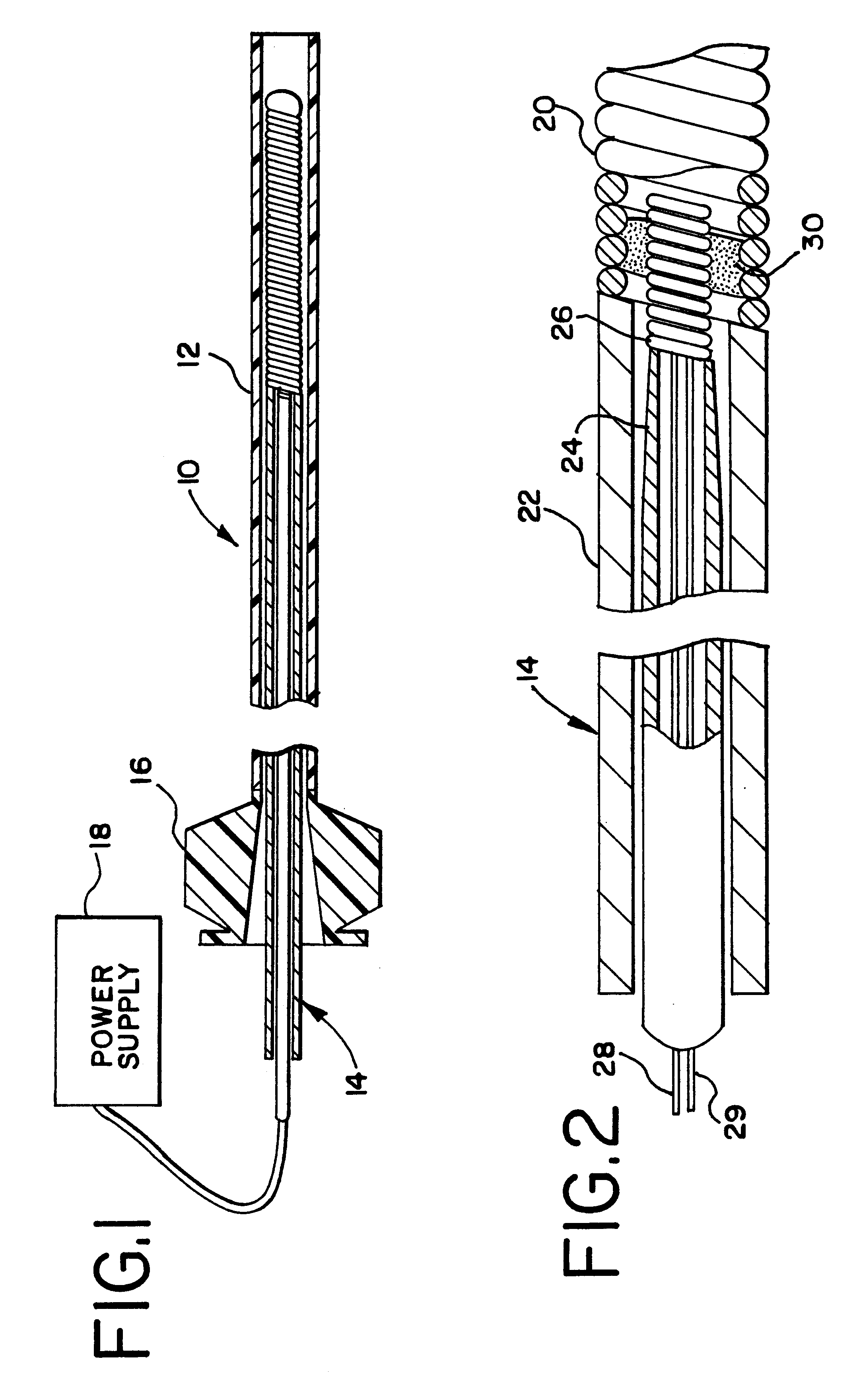
FIG. 1 generally illustrates a preferred embodiment of a vascular occlusion coil deployment system 10 of the present invention which is comprised of an elongated flexible catheter 12 which is utilized to position a coil deployment mechanism 14. A Luer connector 16 is connected to the proximal end of the catheter 12 and the coil deployment mechanism 14 is connected to a power supply 18 for applying energy to the coil deployment mechanism 14.

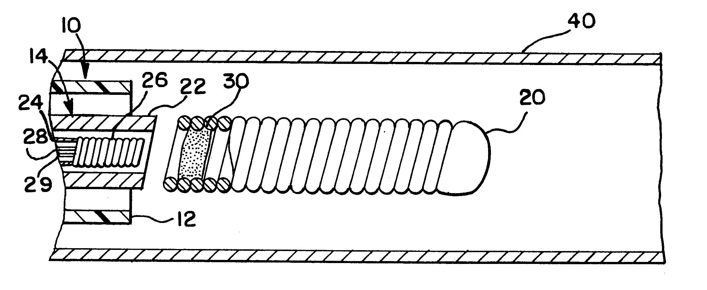
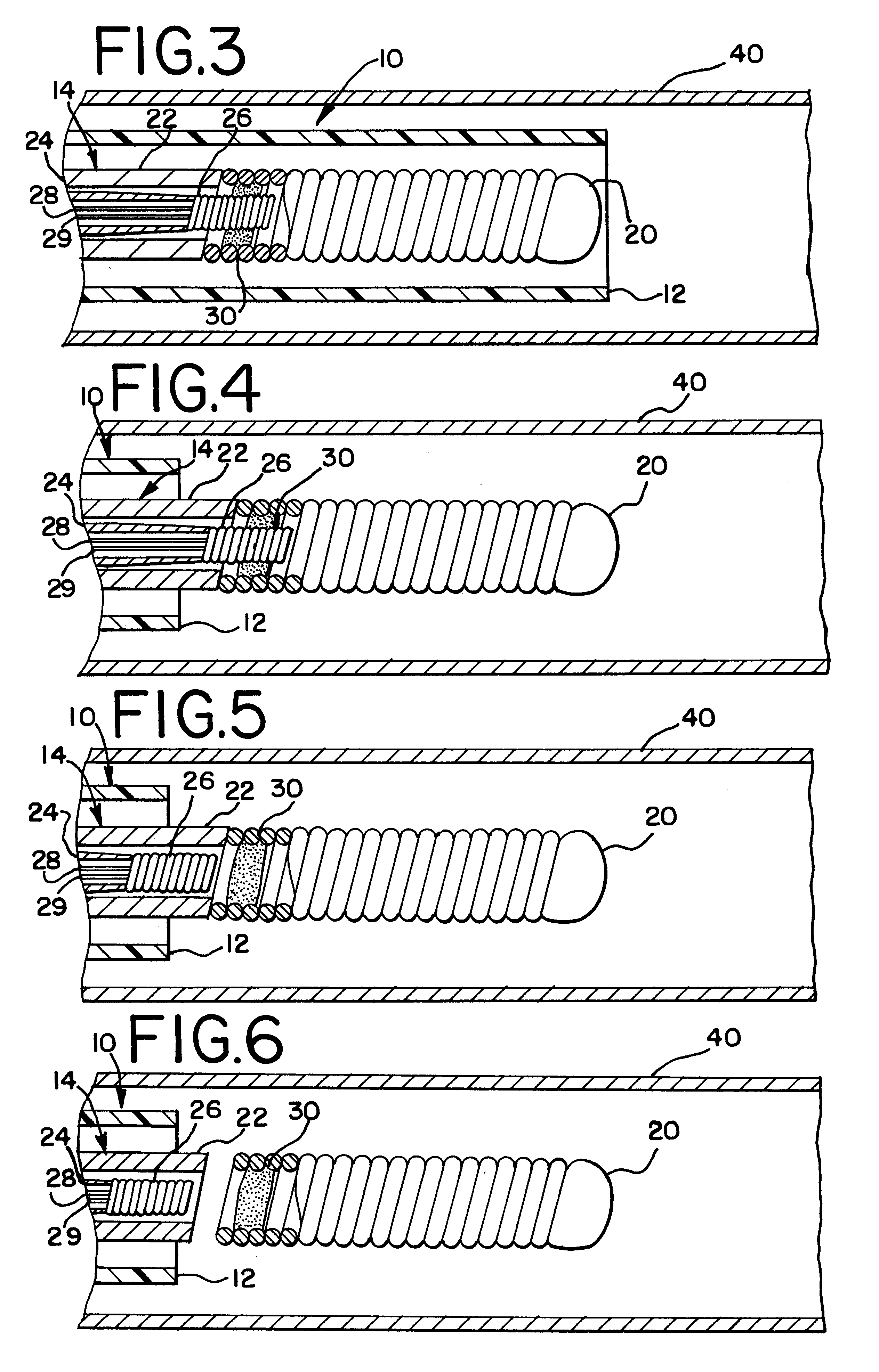
FIG. 2 illustrates in more detail the construction of the coil deployment mechanism 14. More particularly, the deployment mechanism 14 includes an elongated positioning member 22 which is approximately the same length as the outer catheter 12 and which is slidably received by the catheter 12. Positioning member 22 has a lumen extending from its proximal end to its distal end. Coil deployment mechanism 14 also includes a tubular, delivery member 24 which is slidably positioned within the lumen of positioning member 22. Located at the distal end of ...


PUM


Abstract

An embolic coil deployment system for placing a coil at a preselected site within a vessel of the human body. The deployment system includes a heating element at the distal end of a delivery member and a heat responsive coupling for holding the coil during positioning of the coil and activation means for releasing the coil at a desired position within the vessel.

Description

1. Field of the InventionThe present invention relates to a medical device for placing an embolic coil at a preselected location within a vessel of the human body, and more particularly, relates to a flexible delivery member having a heating element and a heat responsive coupling member at the distal tip of the delivery member for holding the embolic coil in order to transport the coil to a desired position within the vessel and release the embolic coil at that position.2. Description of the Prior ArtFor many years flexible catheters have been used to place various devices within the vessels of the human body. Such devices include dilatation balloons, radiopaque fluids, liquid medications and various types of occlusion devices such as balloons and embolic coils. Examples of such catheter devices are disclosed in U.S. Pat. No. 5,108,407, entitled "Method And Apparatus For Placement Of An Embolic Coil"; U.S. Pat. No. 5,122,136, entitled, "Endovascular Electrolytically Detachable Guide...

Claims


Application Information

Patent Timeline
Patent Type & Authority Patents(United States)
IPC IPC(8): A61B17/12A61F2/06
CPCA61B17/12022A61B17/1214A61B2017/12068A61B2017/12063A61B2017/00477
Inventor BARRY, DAVID C.JONES, DONALD K.MITELBERG, VLADIMIR
Owner CODMAN & SHURTLEFF INC
Why Eureka
Try Eureka