Braking device for a motorized snow vehicle

a technology for snow vehicles and braking devices, which is applied in the direction of braking systems, mechanical devices, and braking element arrangements, etc., can solve problems such as the insufficient ability to efficiently brake the vehicl

Inactive Publication Date: 2001-09-04
BIBOLLET JEAN CLAUDE
View PDF12 Cites 18 Cited by
  • Summary
  • Abstract
  • Description
  • Claims
  • Application Information

AI Technical Summary

Benefits of technology

According to another feature of the invention, the braking element is movable in rotation with respect to a transverse spindle extending perpendicularly with respect to the longitudinal plane of symmetry of the ski, movement of the braking element in rotation from the active position to the rest position taking place upwards with respect to the bottom surface of the ski. The braking clement comprises a brake shoe formed by at least one gripping blade designed to achieve a progressive braking effect according to the depth of penetration in the snow.

Problems solved by technology

Although they can slow down and even stop rotation of this track, they prove insufficient to brake the vehicle efficiently on downhill stretches where the caterpillar track is no longer bearing the load, due to its rear position, the weight being transferred due to the slope mainly onto the front of the vehicle, and in particular onto the steering ski or skis of the vehicle.

Method used


Image

  • Braking device for a motorized snow vehicle
  • Braking device for a motorized snow vehicle
  • Braking device for a motorized snow vehicle

Examples


first embodiment

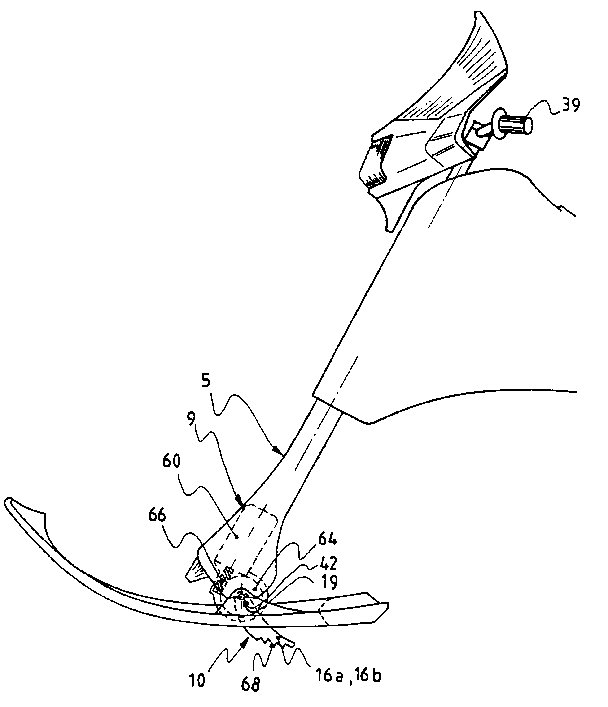
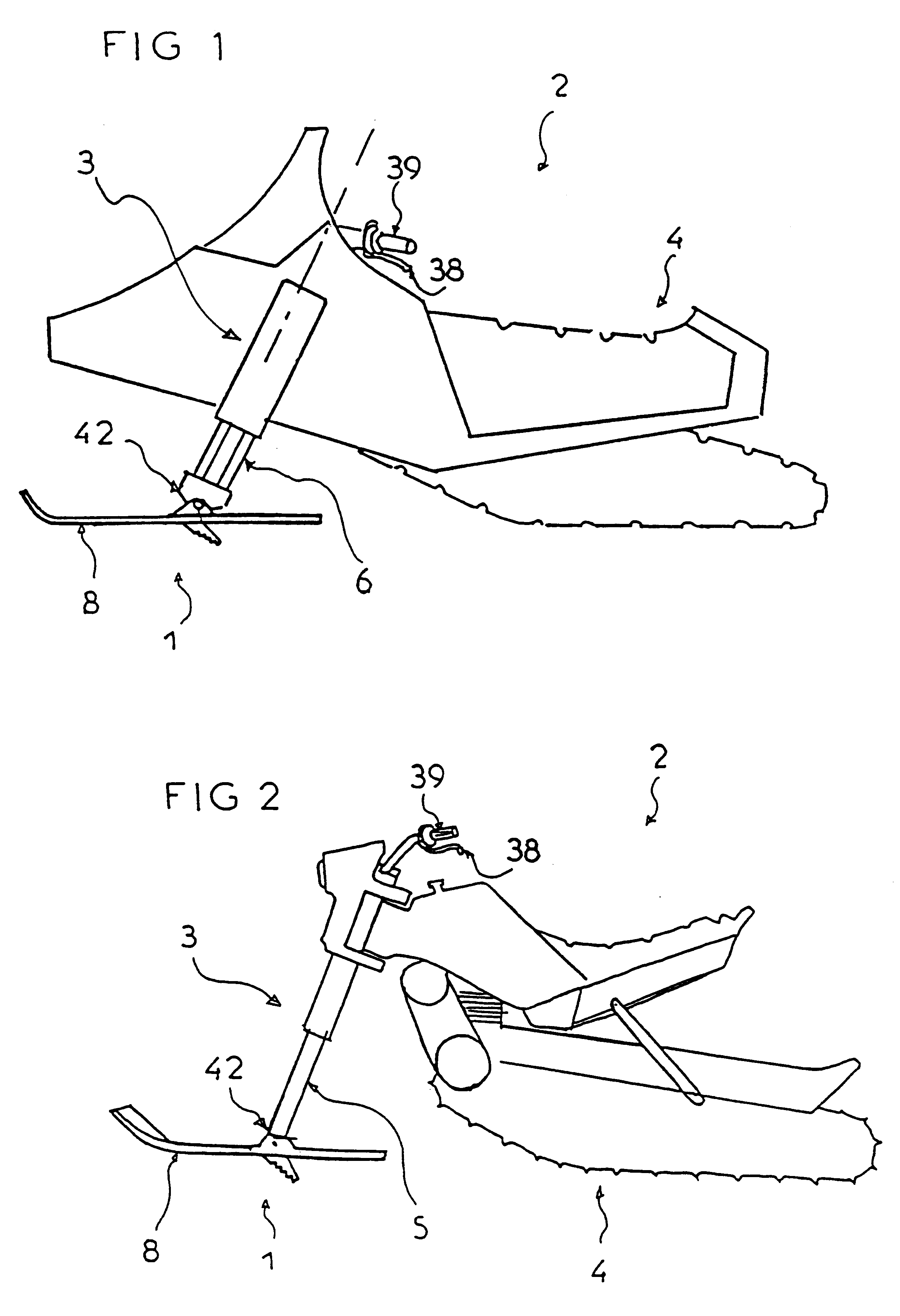
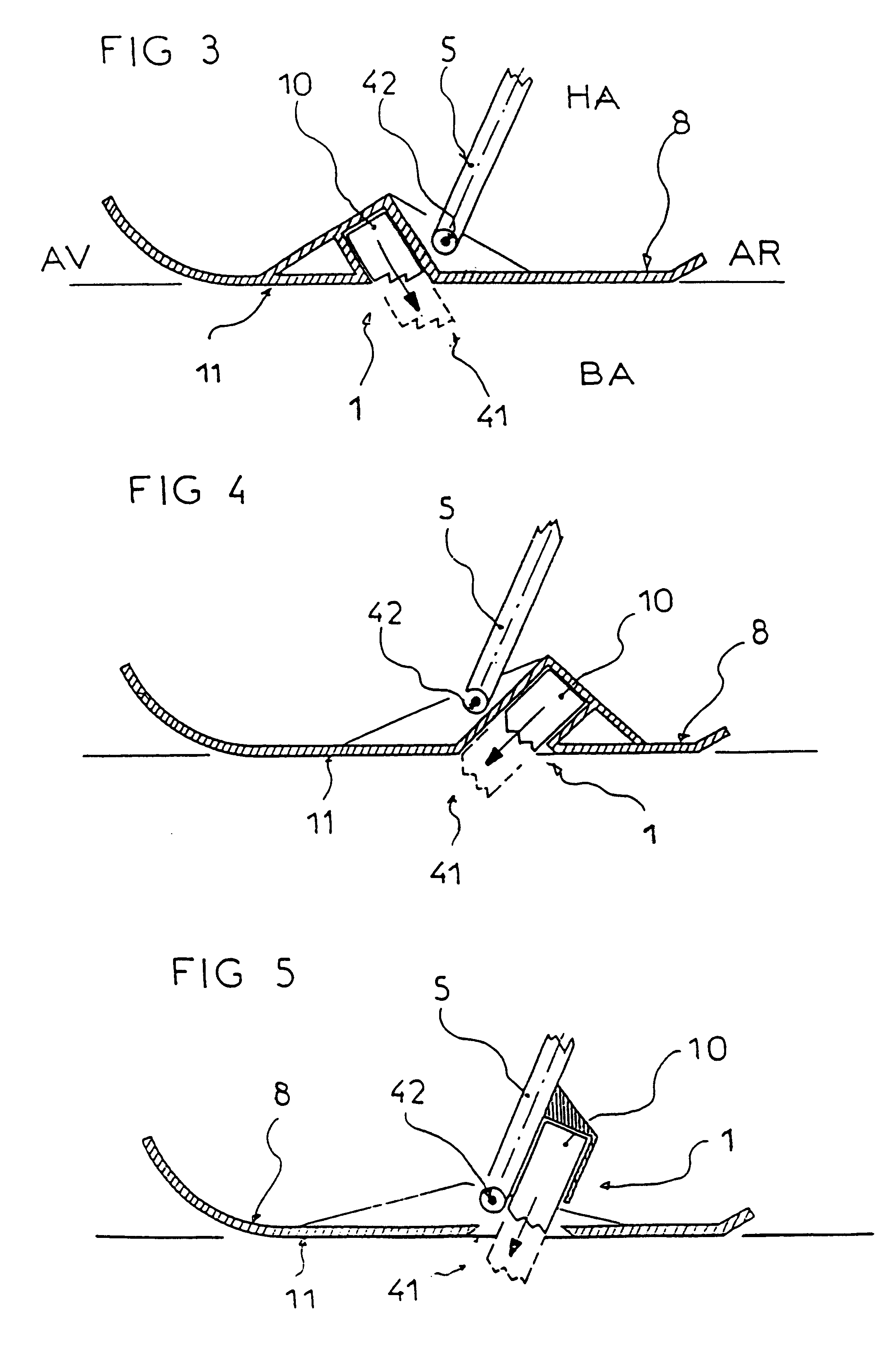
the mobile braking element 10 is movable in translation with respect to the ski 8, or with respect to the steering column 5 as illustrated in FIGS. 3, 4 and 5; it can protrude out to the rear and the bottom of the ski 8, as in the first alternative embodiment illustrated in FIG. 3, or to the front and the bottom, as in the second alternative embodiment illustrated in FIG. 4.

According to a third alternative embodiment illustrated in FIG. 5, the mobile braking element 10 is movable in translation with respect to the steering column 5 on which the ski 8 is articulated in rotation, which provides the advantage of accentuating or on the contrary of minimizing the braking effect automatically according to the angle of incline of the ski with respect to the steering column. When the vehicle goes over a mogul, the braking effect is accentuated with the downward incline of the ski. The braking effect is on the contrary decreased when the front of the ski lifts up, for example when going thro...

second embodiment

the mobile braking element 10 is articulated in rotation around a rotation spindle 19 appreciably transverse with respect to the ski 8 as illustrated in FIGS. 6, 7 and 8. In a first alternative version, the control means 9 enabling rotation of the mobile braking element 10 to be achieved are positioned on the front part (AV) of the ski 8 and act on a lever arm 12 of the mobile braking element 10, as shown in FIG. 6. According to a second alternative version, the control means 9 securedly united to the ski 8 act directly on the mobile braking element 10, as illustrated in FIG. 7. According to a third alternative version illustrated in FIG. 8, the control means 9 are securedly united to the steering column 5, which provides the same advantage of accentuating or on the contrary of minimizing the braking effect automatically according to the angle of incline of the ski with respect to the steering column 5.

With reference to FIGS. 9 to 11, the mobile braking element 10 formed by a lever ...


PUM


Abstract

A braking device for a motorized snow vehicle having a front steering assembly with at least one steering column secured to at least one ski, and articulated in rotation around a spindle. The motorized snow vehicle further has a rear support assembly, equipped with at least one driving caterpillar track. The front steering assembly comprises at least one mobile braking element operated, by control means, between a retracted rest position inside a cavity of the ski, and an active braking position protruding out under the general sliding surface of the ski in a middle zone situated appreciably at the level of the articulation spindle between the steering column and the ski.

Description

The present invention relates to a braking device for a snow vehicle in particular of the snowbike type, comprising:a front steering assembly comprising at least one steering column secured to at least one ski, and articulated in rotation around a spindle,and a rear support assembly, equipped with at least one driving caterpillar track.STATE OF THE TECHNIQUEAt the present time, braking devices of this type of vehicle act on the driving caterpillar track. Although they can slow down and even stop rotation of this track, they prove insufficient to brake the vehicle efficiently on downhill stretches where the caterpillar track is no longer bearing the load, due to its rear position, the weight being transferred due to the slope mainly onto the front of the vehicle, and in particular onto the steering ski or skis of the vehicle.OBJECT OF THE INVENTIONThe object of the device according to the invention is therefore to fit an efficient brake on a motorized snow vehicle.According to the in...

Claims


Application Information

Patent Timeline
Patent Type & Authority Patents(United States)
IPC IPC(8): B62M27/00B62M27/02F16D65/14F16D63/00
CPCB62M27/02F16D63/008B62M2027/025F16D2125/40F16D2121/24
Inventor BIBOLLET, JEAN-CLAUDE
Owner BIBOLLET JEAN CLAUDE
Why Eureka
Try Eureka