ATV transmission

a transmission and atv technology, applied in the direction of cycle equipment, cycle, gearing, etc., can solve the problems of bulky and heavy units, difficult production operations, and difficulty in producing compact vehicles

Inactive Publication Date: 2001-09-11
YAMAHA MOTOR CO LTD
View PDF23 Cites 62 Cited by
  • Summary
  • Abstract
  • Description
  • Claims
  • Application Information

AI Technical Summary

Benefits of technology

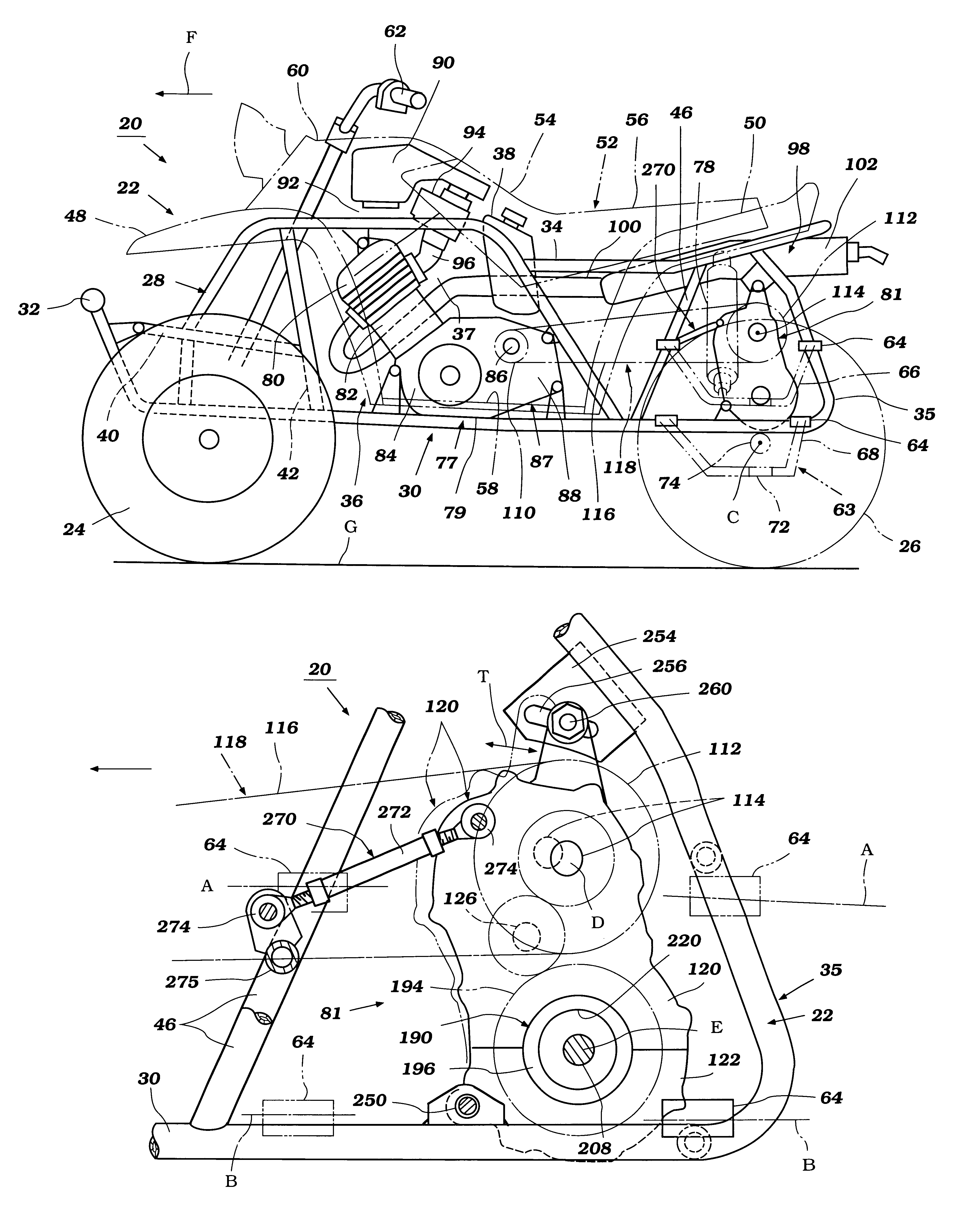
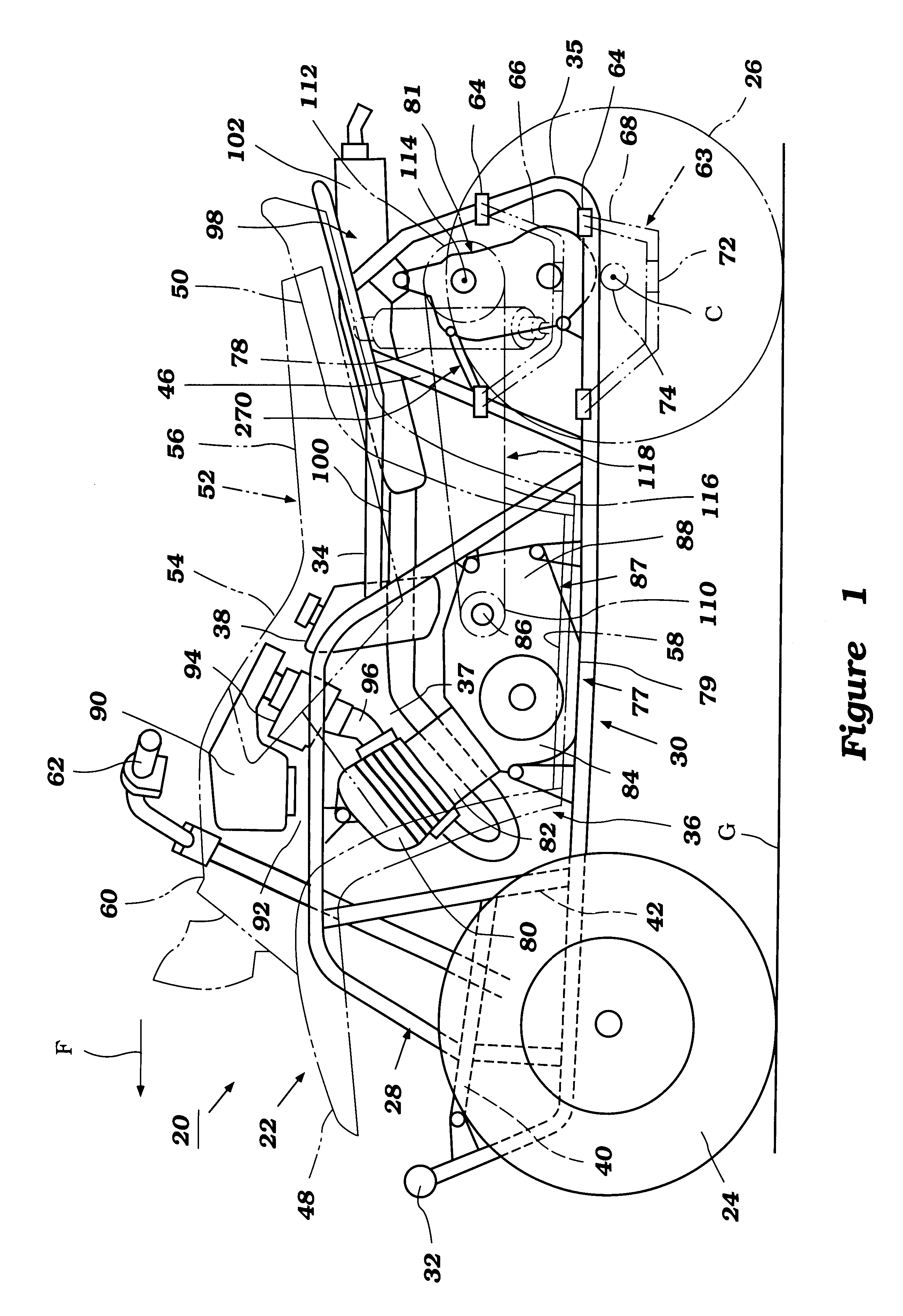
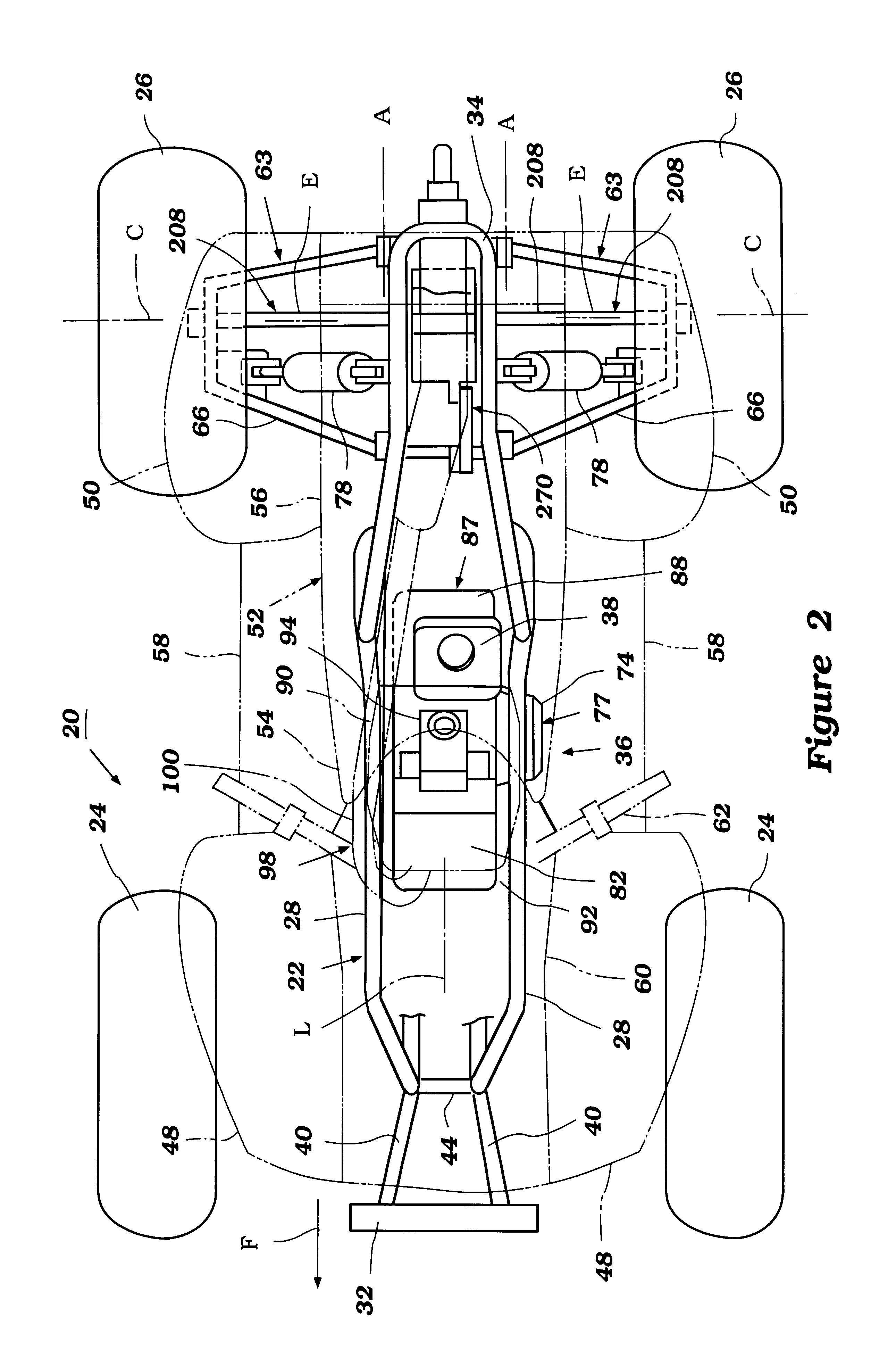
With reference now to FIGS. 1 through 3, an all terrain vehicle is illustrated and is generally identified by the reference numeral 20. The vehicle 20 incorporates a transmission that is arranged and configured in accordance with certain features, aspects and advantages of the present invention. The illustrated vehicle 20 preferably is adapted for off-road operation; however, certain features, aspects and advantages that will become apparent below can be used in street vehicles. In addition, as the illustrated vehicle 20 is only a typical application for the present invention, other applications will become readily apparent to those of ordinary skill in the art. For this reason, many details of the illustrated vehicle 20 that do not require an understanding for one of ordinary skill in the art to practice the present invention will be omitted; however, the omitted details should be considered well-known to those of ordinary skill in the art.

Problems solved by technology

In addition, manufacturing such compact vehicles has been a difficult task.
Either method is difficult in production operations.
Assembling the engine and transmission as a unit yields a bulky and heavy unit that must be shoehorned into the engine compartment.
Yet, placing both components into the engine compartment before securing them together is made difficult due to the small size of the engine compartment.
The driven sprocket generally is larger than the drive sprocket and, thus, in some arrangements, can disadvantageously depend downwardly into the clearance zone defined between the vehicle's frame and the ground.
In addition, tension on the chain can decrease over time such that the vehicle needs to be extensively serviced before the chain disengages from the sprockets.

Method used


Image

  • ATV transmission
  • ATV transmission
  • ATV transmission

Examples


Embodiment Construction

With reference now to FIGS. 1 through 3, an all terrain vehicle is illustrated and is generally identified by the reference numeral 20. The vehicle 20 incorporates a transmission that is arranged and configured in accordance with certain features, aspects and advantages of the present invention. The illustrated vehicle 20 preferably is adapted for off-road operation; however, certain features, aspects and advantages that will become apparent below can be used in street vehicles. In addition, as the illustrated vehicle 20 is only a typical application for the present invention, other applications will become readily apparent to those of ordinary skill in the art. For this reason, many details of the illustrated vehicle 20 that do not require an understanding for one of ordinary skill in the art to practice the present invention will be omitted; however, the omitted details should be considered well-known to those of ordinary skill in the art.

With continued reference to FIG. 1, the ve...


PUM


Abstract

An all terrain vehicle includes an engine and a final drive assembly. The engine includes an output shaft that supports a drive sprocket or pulley. The final drive assembly comprises an input shaft that supports a driven sprocket or pulley and a brake disc. A flexible transmitter such as a belt or a chain connects the drive sprocket or pulley and the driven sprocket or pulley. The final drive assembly is formed separate of the engine and spaced apart from the engine when the two components are mounted to a frame of the vehicle. The driven sprocket or pulley is positioned on an upper portion of the final drive assembly while a lower portion of the final drive assembly is pivotally connected to the frame. The final drive assembly can be pivoted to adjust a tension level within the flexible transmitter. The final drive assembly can be selectively secured in a pivotal position by a support rod and / or a set of slotted brackets.

Description

1. Field of the InventionThe present invention generally relates to drive arrangements for all terrain vehicles. More specifically, the present invention relates to separated engines and final drive assemblies for use in all terrain vehicles.2. Related ArtAll terrain vehicles are constructed for use in all kinds of rough, rocky and uneven terrain. The vehicles generally comprise a frame that defines an engine compartment, an engine positioned within the engine compartments and a transmission that drives a set of wheels with power from the engine. The transmission typically is included within a transmission case that is directly connected to the engine and generally powers the rear wheels through a shaft and differential assembly. Preferably, substantial clearance is maintained between the vehicle and its associated components and the ground over which the vehicle is being operated.Recently, manufacturers have been down sizing the all terrain vehicles to create a more compact vehicle...

Claims


Application Information

Patent Timeline
Patent Type & Authority Patents(United States)
IPC IPC(8): B60K17/04B62K5/00B62M7/02B62M7/00B62M9/00
CPCB60K17/04B62K5/01Y10T74/2188
Inventor UCHIYAMA, MASAYUKIFUKUSHIMA, MASAMITSU
Owner YAMAHA MOTOR CO LTD
Why Eureka
Try Eureka