Fuel delivery device

a technology of fuel delivery device and fuel pump, which is applied in the direction of liquid fuel feeder, bends, machines/engines, etc., can solve the problem of disadvantage of fuel delivery devi

Inactive Publication Date: 2001-09-25
ROBERT BOSCH GMBH
View PDF7 Cites 25 Cited by
  • Summary
  • Abstract
  • Description
  • Claims
  • Application Information

AI Technical Summary

Problems solved by technology

This construction of the fuel delivery device is disadvantageous because it requires a special c...

Method used


Image

  • Fuel delivery device
  • Fuel delivery device
  • Fuel delivery device

Examples


Embodiment Construction

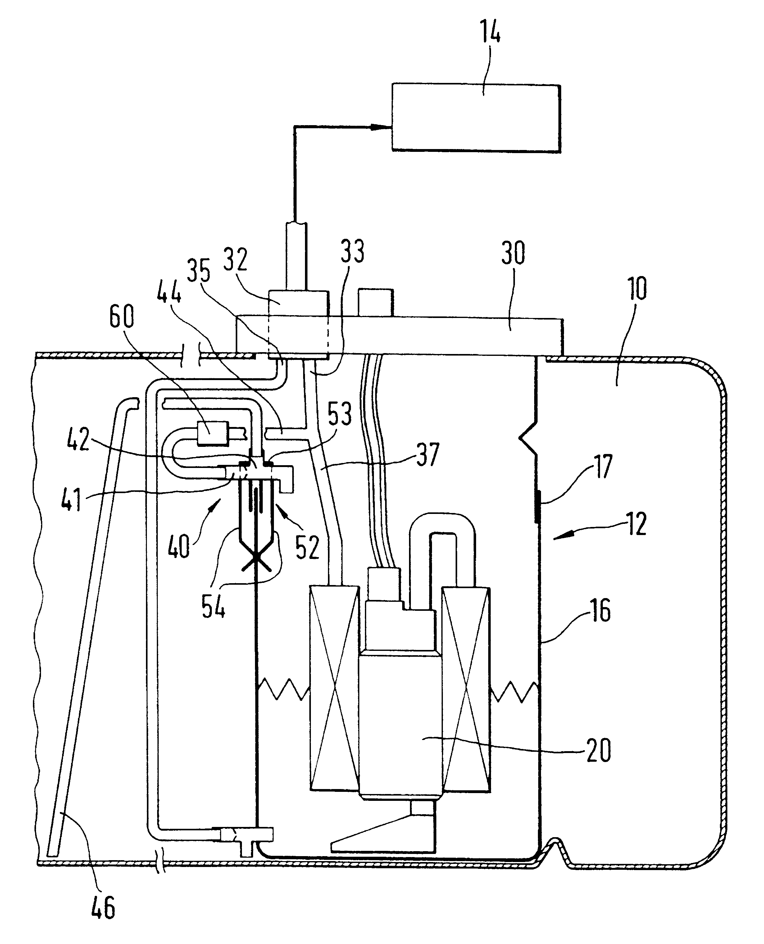
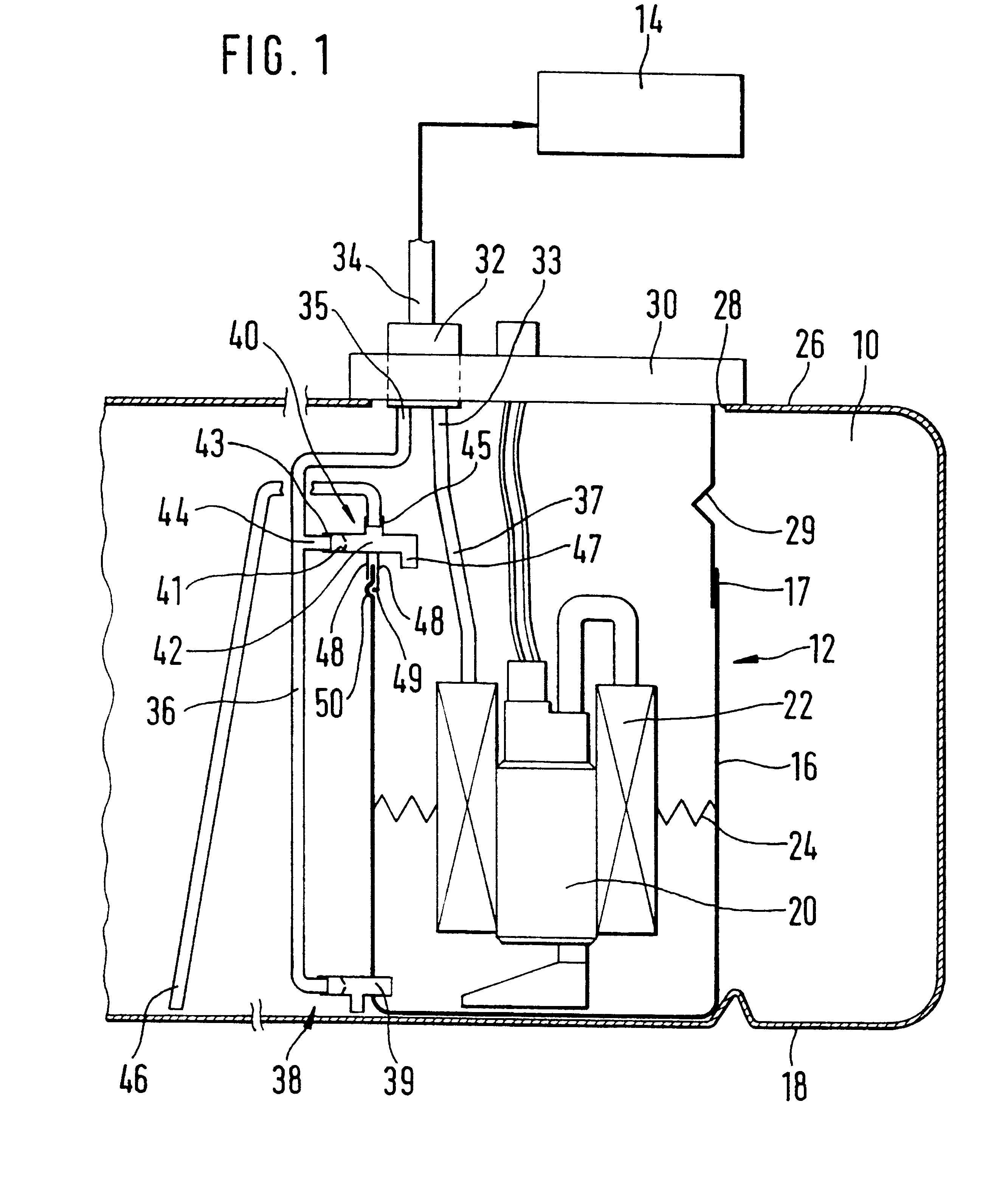
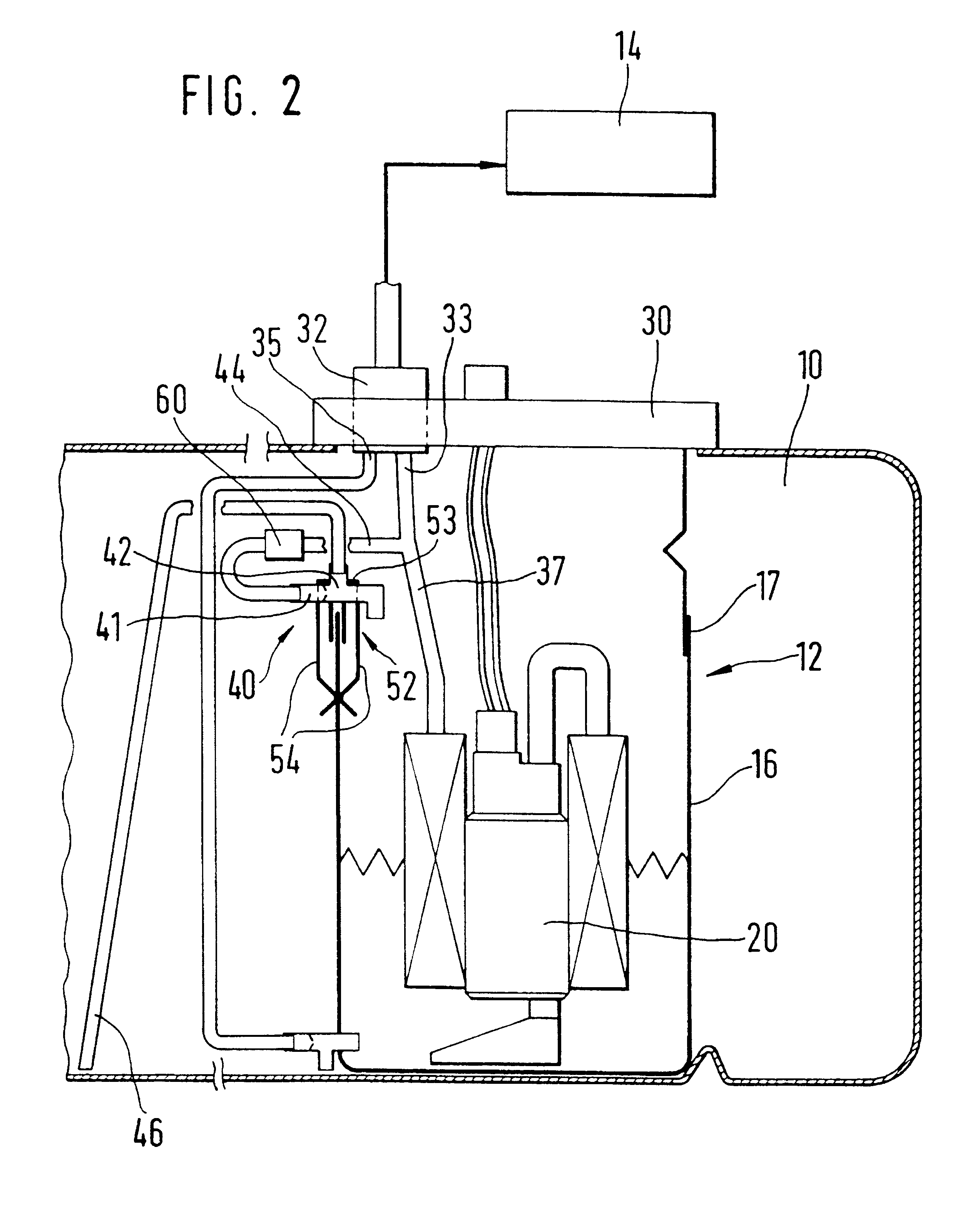
FIGS. 1 to 3 show a fuel storage tank 10 of a motor vehicle in section, a fuel delivery device 12 for delivering fuel from the storage tank 10 to the fuel injection system of the internal combustion engine 14 of the motor vehicle being arranged therein. The fuel delivery device 12 has a pot-shaped receptacle 16 which fits on a base 18 of the storage tank 10 and can be fixed to the base 18 in a manner not shown in more detail. The receptacle 16 can be made of fuel-resistant plastic, for example, and is open at its upper end. A delivery unit 20 which sucks fuel out of the receptacle 16 during operation and delivers it to the internal combustion engine 14 is installed in the receptacle 16. The delivery unit 20 has a pump part and a motor part which drives the latter, especially with an electric drive motor. Further, a filter 22 can be arranged in the receptacle 16. The fuel delivered by the delivery unit 20 is filtered through the filter 22 before being delivered to the internal combus...


PUM


Abstract

The fuel delivery device (12) has a receptacle (16) arranged in a storage tank (10) and a delivery unit (20) delivering fuel from the receptacle (16) to the internal combustion engine (14) of a motor vehicle. Further, there is provided at least one suction jet pump (40) which delivers fuel from the storage tank (10) into the receptacle (16). The suction jet pump (40) is fastened to an upper edge area (17) of the receptacle (16) as a separate constructional unit. The suction jet pump (40) is formed by a constructional unit having a propelling nozzle (41), a connection (43) for a propelling line (44), which connection (43) opens into the propelling nozzle (41), a mixing pipe (42) following the propelling nozzle (41), and a connection (45) for a suction line (46), which connection (45) opens into the mixing pipe (42). Two walls (48) located at a distance from one another project downward from the constructional unit (40), and the constructional unit (40) is mounted on the edge (17) of the receptacle (16) from the top, wherein the edge (17) of the receptacle (16) is introduced between the two walls (48). The suction line (46) connected to the suction jet pump (40) opens into the storage tank (10) remote of the receptacle (16).

Description

1. Description of the Prior ArtThe invention is directed to a fuel delivery device according to the generic part of claim 1.A fuel delivery device of the type mentioned above is known from DE 42 19 516 A1, This fuel delivery device serves to deliver fuel from a storage tank to the internal combustion engine of a motor vehicle. A receptacle from which a delivery unit delivers fuel to the internal combustion engine is arranged in the storage tank. A plurality of suction jet pumps through which fuel is delivered from the storage tank to the receptacle are integrated in the receptacle. Suction lines are connected to the suction jet pumps and open out at various locations in the storage tank. This ensures that the receptacle can be reliably filled with fuel even when the storage tank is relatively empty and when there is an uneven distribution of fuel in the storage tank, for example, as a result of the vehicle ascending a grade or driving along a curve. This construction of the fuel del...

Claims


Application Information

Patent Timeline
IPC IPC(8): B60K15/077B60K15/03F02M37/18F04F5/54
CPCB60K15/077B60K2015/03236B60K2015/03467B60K2015/03105Y10T137/2917
Inventor KLEPPNER, STEPHANFRANK, KURTMIHATSCH, STEFFENHUFNAGEL, KLAUS-DIETERBALLIER, GUENTER-PAULGERHARD, ALBERTJAUCH, GERHARD
Owner ROBERT BOSCH GMBH
Why Eureka
Try Eureka