
System for testing real and simulated versions of an integrated circuit

a technology of integrated circuits and test systems, applied in the field can solve the problems of inability of integrated circuit testers to perform the same test on real ics, inability to carry out, and inability of ic testers to carry out the same tes

Inactive Publication Date: 2001-09-25
CREDENCE SYSTEMS
View PDF7 Cites 42 Cited by
  • Summary
  • Abstract
  • Description
  • Claims
  • Application Information

AI Technical Summary

Problems solved by technology

However due to differences in capabilities of simulators and circuit testers and the manner in which they are programmed, an integrated circuit tester often cannot perform the same test on a real IC that a circuit simulator performs on its simulated counterpart.
An IC tester has several limitations not shared by a simulator that can render it unable to carry out the same test that a simulator can carry out.
First, while a simulator can simulate and test an IC model having any number of I / O terminals, an IC tester can access only a limited number of IC pins.
Second, an IC tester may not be able to carry out the same test as a simulator because it has a limited capacity to store test vectors.
It may well be that the vector sequence needed to define a test a simulator can carry out can be too large for the tester's vector memories.
The length of a test that an IC tester can carry out is therefore limited by the size of its vector memories.
Thus due to its "bounded data domain", an IC tester may not be able perform tests as long as those that may be performed by a simulator.
Third, an IC tester may not be able to perform a test carried out by a simulator because it cannot carry out test events in real time as frequently as a simulator can in simulated time.
However an IC tester, which must operate in real time, is limited in how frequently it can change the state of a test signal or sample an IC output signal.
Its "bounded time domain" therefore limits the tester's ability to carry out some sequences of test events.
Thus due to its bounded pin, data and time domains, a tester often cannot test a real IC in the same way that a simulator can test an IC model.
It is therefore usually not possible to directly convert a test bench file into a set of instructions for an IC tester.
The need for a test engineer other than the IC designer to program an IC tester to perform a test that differs from the test performed by a simulator adds much time and expense to the IC development process and also makes it less certain as to whether the real and simulated ICs are truly comparable in performance.

Method used


Image

  • System for testing real and simulated versions of an integrated circuit
  • System for testing real and simulated versions of an integrated circuit
  • System for testing real and simulated versions of an integrated circuit

Examples


Embodiment Construction

)

Hardware Architecture

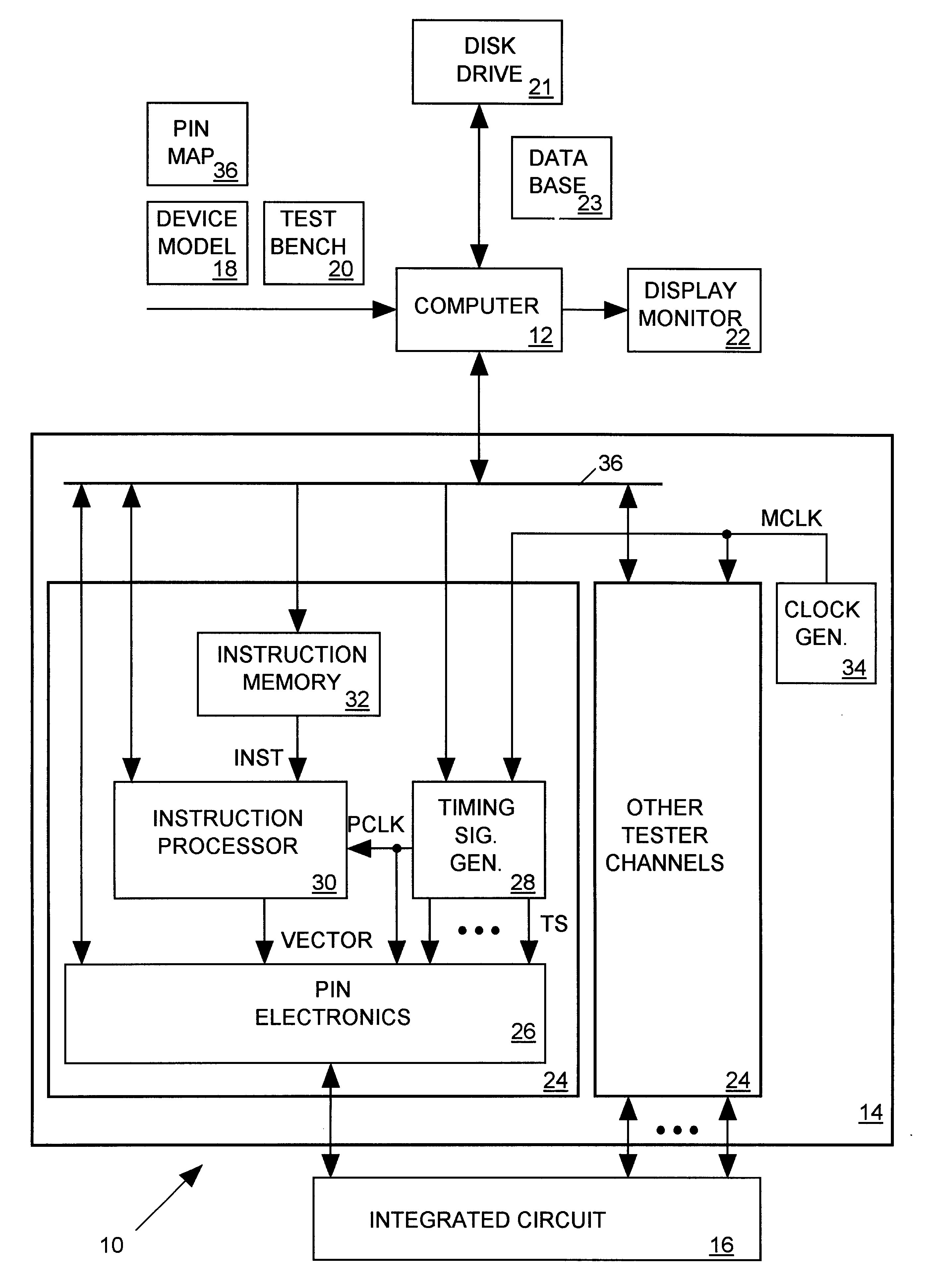
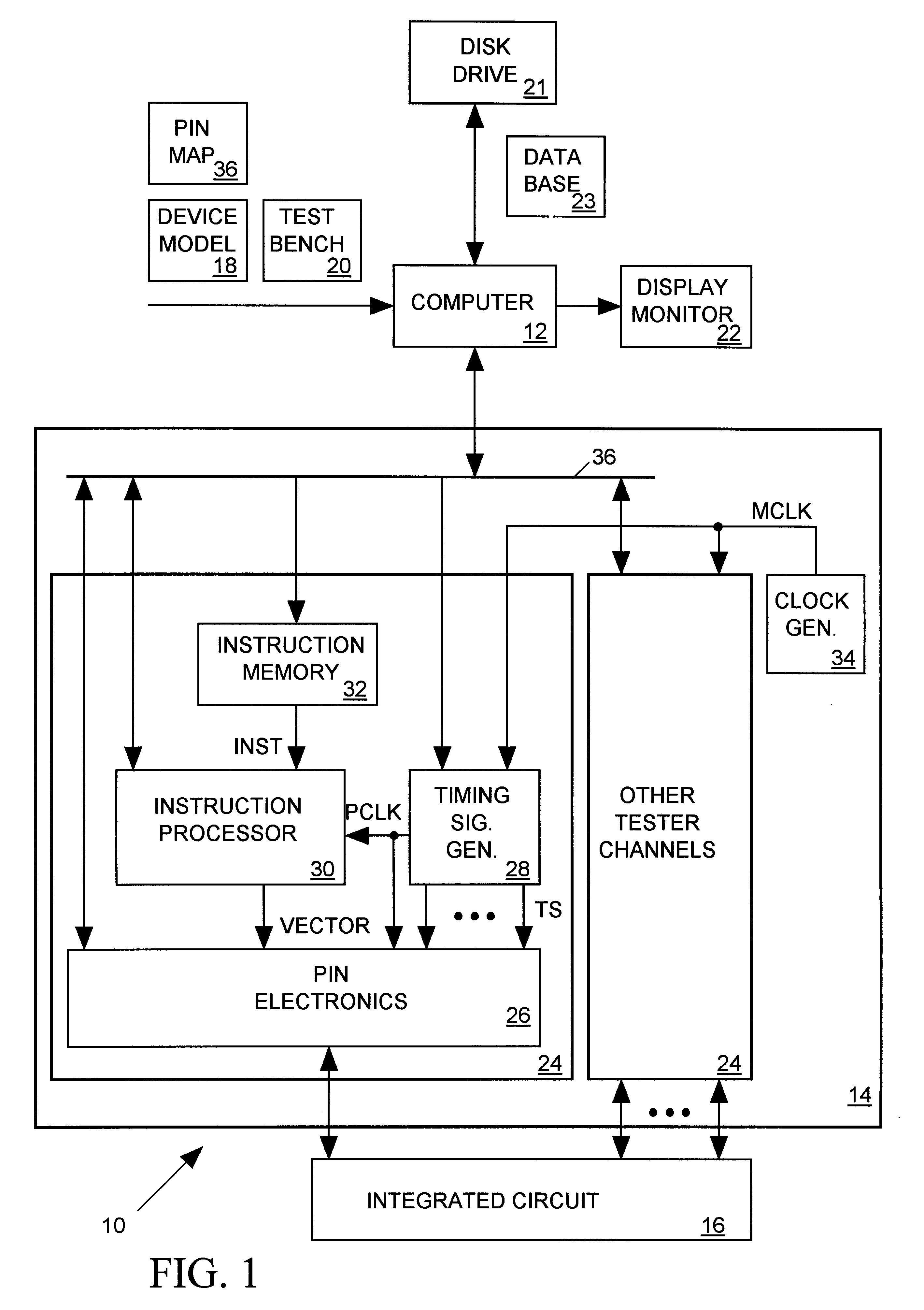
FIG. 1 illustrates an integrated circuit (IC) testing system 10 in accordance with the present invention for testing both real and simulated versions of an IC. Test system 10 includes a computer 12, an IC tester 14 and a display monitor 22. Computer 12 executes software for testing the simulated version of the IC in response to input test instructions from a user and for automatically programming IC tester 14 so that it tests the real version of the IC 16 in a similar manner. Test system 10 displays results of test of both real and simulated versions of the IC on display monitor 22 in a similar manner so that it is easy for the user to compare them.

The user provides three input files to computer 12. A conventional device model 18 written in the well-known Verilog hardware description language describes the IC to be simulated as a set of components connected between circuit nodes. Device model 18 describes the behavior of each component by one or more mathematic...


PUM


Abstract

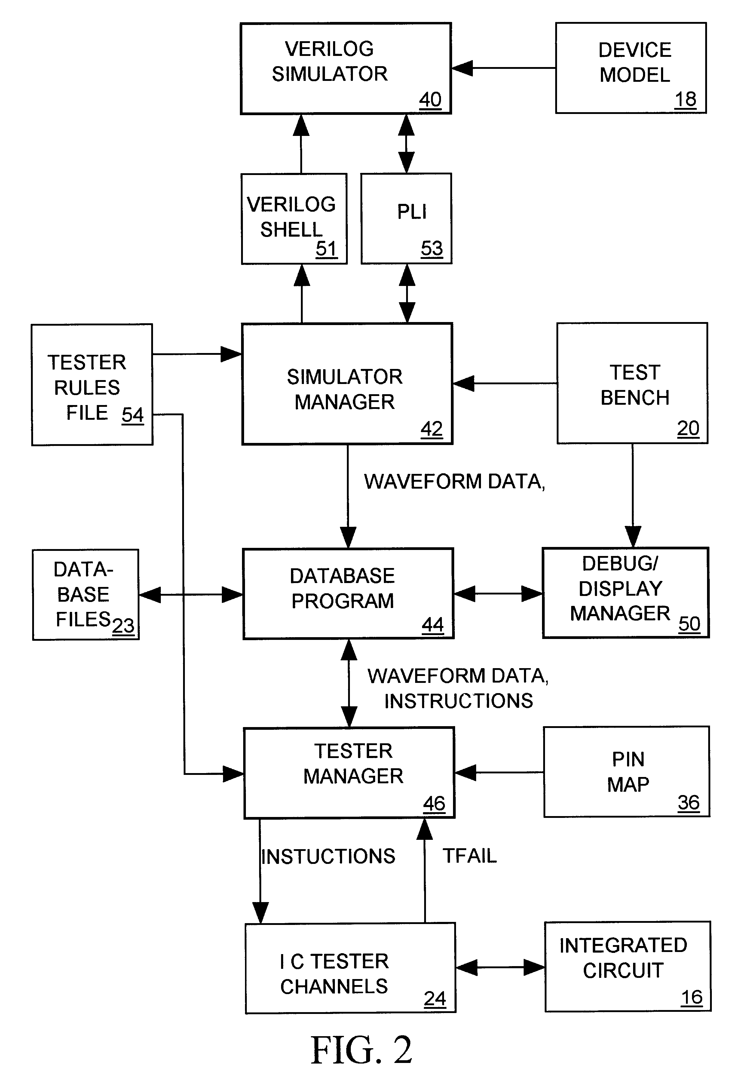
A system for testing both simulated and real versions of an integrated circuit (IC) includes an IC simulator, a simulator manager, an IC tester, and a tester manager. The IC simulator simulates response of the IC to a set of simulated IC input signals by producing a set of simulated IC output signals. The simulator manager, programmed by a user-supplied test bench file, provides the simulated IC input signals to the simulator during the simulation. During the simulation, the simulator manager also generates a set of waveform data sequences, each representing periodically sampled values of a corresponding one of the simulated IC input and output signals. The IC tester includes a separate channel corresponding to each real IC input and output signal. The tester manager converts the waveform data sequence corresponding to each simulated IC input and output signal to a separate set of instructions provided as input to a corresponding one of the IC tester channels. When testing the real IC, each IC tester channel corresponding to a real IC input signal responds to its input instructions by generating and supplying to the IC an input signal having the sequence of values indicted by the waveform data sequence representing the corresponding simulated IC input signal. Each IC tester channel corresponding to an IC output signal responds to its input instructions by periodically sampling the corresponding IC output signal to determine whether the IC output signal has the sequence of values indicated by the waveform data sequence representing the corresponding simulated IC output signal.

Description

1. Field of the InventionThe present invention relates in general to integrated circuit (IC) testers and in particular to an IC tester that is seamlessly integrated with an IC simulator so that they may be programmed in the same manner to perform similar tests on simulated and real versions of an IC.2. Description of Related ArtAn integrated circuit (IC) designer typically develops a model of an IC and then tests the model using an integrated circuit simulator. When the test indicates the model operates correctly, the designer uses synthesis and mapping tools to convert the model into a set of masks needed to fabricate a real IC. After the IC has been fabricated a test engineer tests the IC using an integrated circuit tester. It would be helpful if an IC tester could perform the same test on the real IC that the simulator performed on the simulated IC. However due to differences in capabilities of simulators and circuit testers and the manner in which they are programmed, an integra...

Claims


Application Information

Patent Timeline
IPC IPC(8): G01R31/28G01R31/3193
CPCG01R31/3193
Inventor LESMEISTER, GARY J.LONG, JOHN MATTHEW
Owner CREDENCE SYSTEMS
Learn More