
Dispenser for dental floss

a dispenser and dental floss technology, applied in the direction of containers, tray containers, diagnostics, etc., can solve the problems of awkward disengaging of dental floss so as to remove a length of dental floss from the dispenser, the user's fingers are prone to injury, and the user's fingers are prone to irritation

Inactive Publication Date: 2001-10-02
FLOSS TODAY CORP
View PDF15 Cites 21 Cited by
  • Summary
  • Abstract
  • Description
  • Claims
  • Application Information

AI Technical Summary

Benefits of technology

An object of the present invention is to provide such a dispenser for dental floss as described above, which may be easily and inexpensively brought to the market.
Yet a further object of the present invention is to provide such a dental floss dispenser as described above, where the dental floss dispenser may be secured to a mounting surface, and where removal of the dental floss from the dispenser may be easily effected using only a single hand. Typically, the mounting surface to which a dental floss dispenser in keeping with the present invention may be mounted, is a vertical surface.

Problems solved by technology

However, the cutting blade is quite prominent, thus representing a danger to the fingers of the user.
Here, once again, the cutter for the dental floss is prominently mounted over the surface of the container, representing a threat to the fingers of the user.
Moreover, once again, the disengaging of dental floss so as to remove a length thereof from the dispenser is awkward, requiring reasonable dexterity with the fingers of the hand of the user.
Moreover, the configuration of the dispenser, having a hinged cover, requires the use of two hands to remove dental floss from the dispenser, and precludes the possibility that the dispenser can be mounted to such as a vertical, or any, surface.

Method used


Image

  • Dispenser for dental floss
  • Dispenser for dental floss
  • Dispenser for dental floss

Examples


Embodiment Construction

:

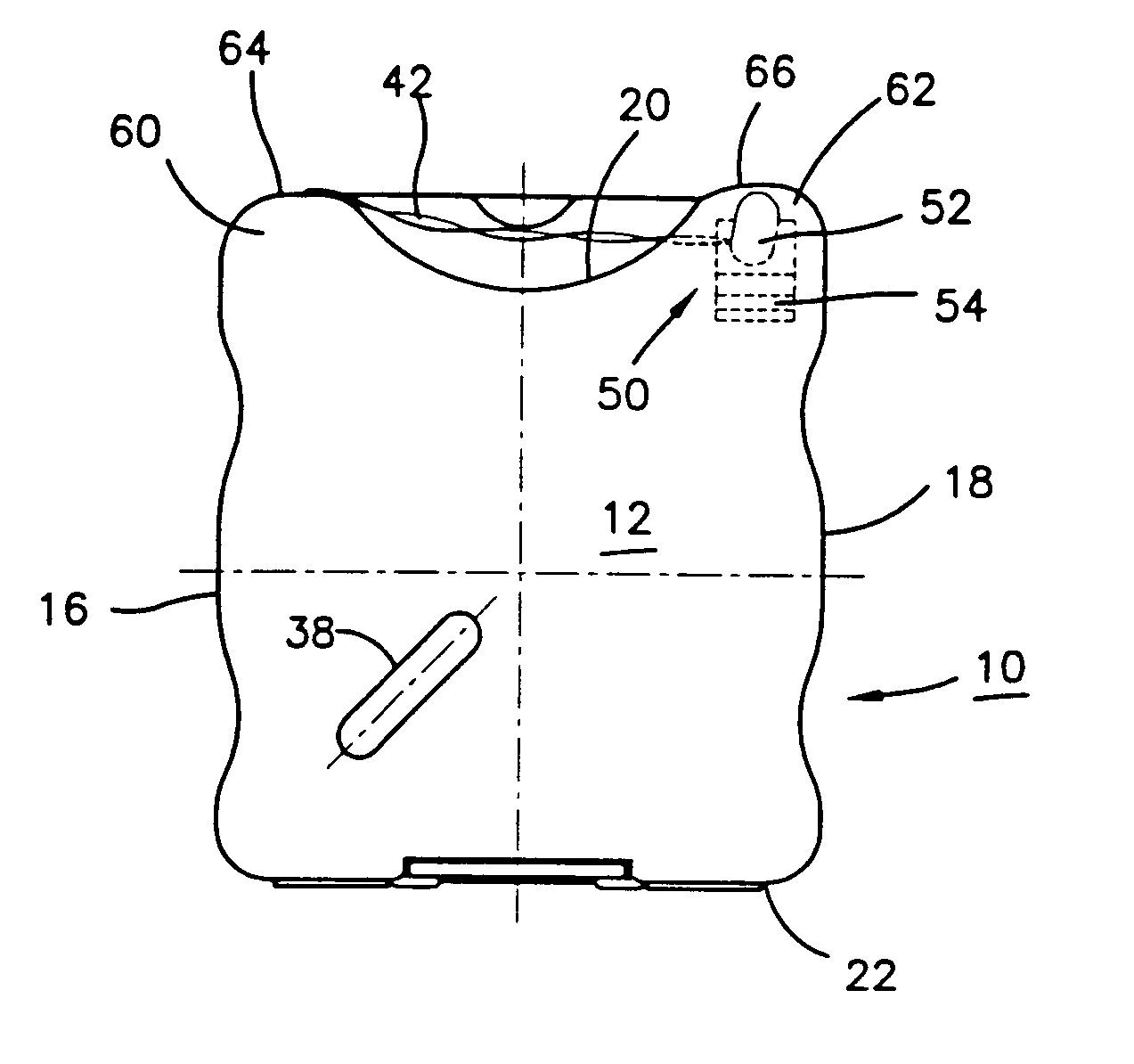
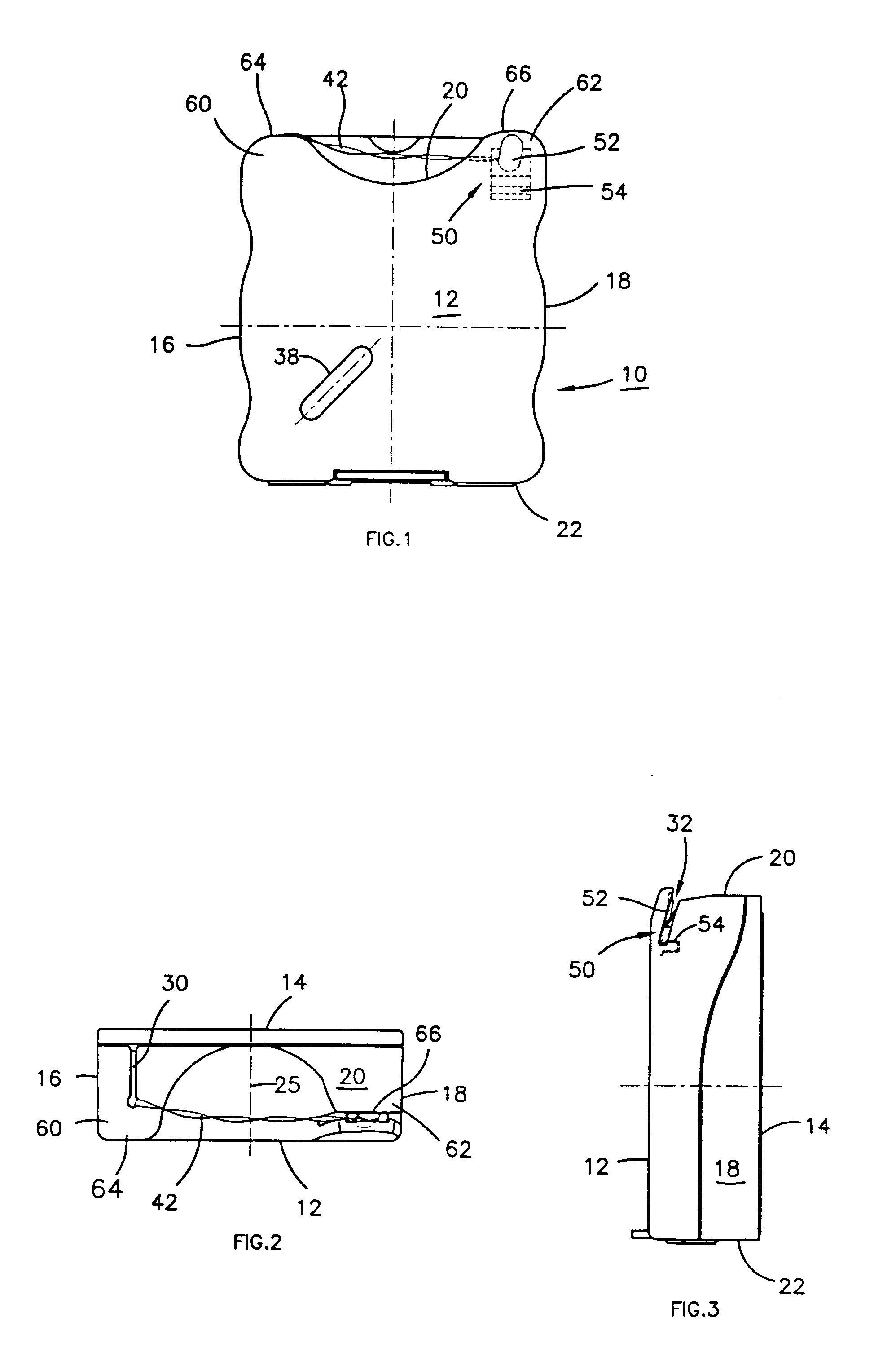
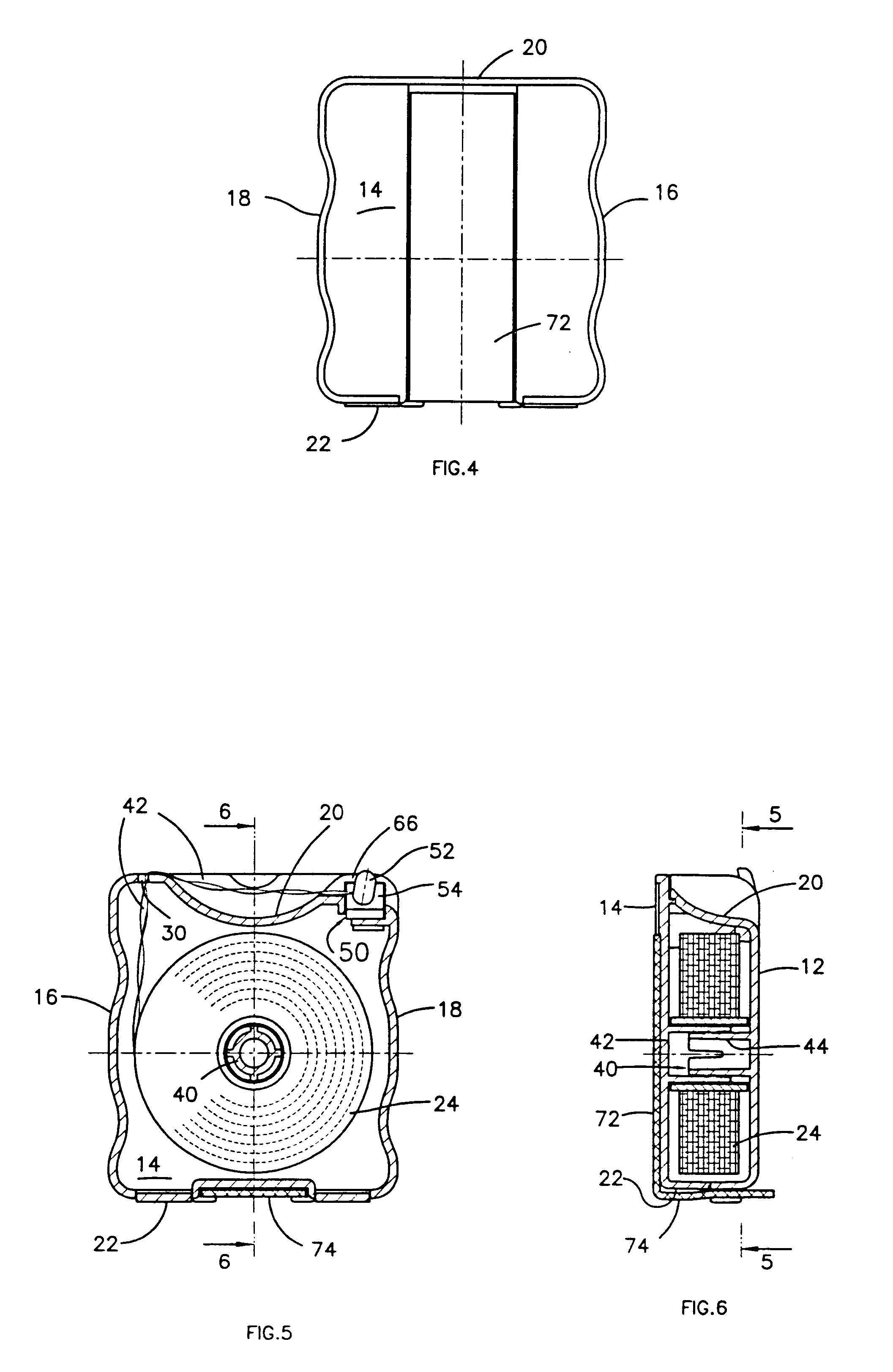
Referring now to FIGS. 1 through 6, a dental floss dispenser 10 in keeping with the present invention is shown. The dental floss dispenser comprises a closed container which has a reel of dental floss 24 disposed therein. The container has a generally planar back face 14, a generally planar front face 12, a pair of opposed side faces 16, 18, a bottom face 22, and a top face 20 which is opposed to the bottom face 22.

There is a hub 40 which is centrally located in the interior of the closed container, and which extends between the interior surfaces of the front and back faces 12, 14. Typically, the hub 40 may comprise a spool 42, mounted on a spindle 44.

Clearly, the reel of dental floss 24 is mounted for rotation about the hub 40, when the dental floss 42 is unwound and removed from the reel 24.

A slot 30 is formed in the top face 20 near a first corner 60, which is in the region of the intersection of the side face 16 and the top face 20. The dental floss 42 extends through the slot ...


PUM


Abstract

A dispenser for dental floss comprises a closed container having a reel of dental floss disposed therein, and having a generally planar back and front face, a pair of opposed side faces, a bottom face, and a top face opposed to the bottom face. There is a hub centrally located in the interior of the closed container, the reel of dental floss is mounted for rotation about the hub when the dental floss is unwound and removed from the reel. A slot is formed in the top face near a first corner of the container, through which slot a strand of dental floss extends so as to be unwound from the reel. A channel is formed at a second corner of the container, at the intersection of the top face and a second side face, and the channel extends between the top face and the second side face. A friction and cutting member comprises a tongue portion which is angled away from a base portion thereof, and is secured in place within the channel. The top face is concave on a centrally located axis extending between the back face and the front face, the concavity being defined by ridges located at the first and second corners. Thus the slot is located in the first ridge at the first corner, and the channel extends through the second ridge at the second corner.

Description

The present invention relates to a dispenser for dental floss. In particular, the present invention provides a dispenser which may conveniently be, but not necessarily, mounted to a mounting surface. The mounting surface is preferably, but not necessarily, vertical. Especially when mounted to a mounting surface, dental floss may be removed from the dental floss dispenser using but a single handThe use of dental floss is highly recommended by the dental profession as a necessary adjunct to oral hygiene. Indeed, the dental profession recommends that teeth should be flossed using an appropriate dental floss, at least once daily; for example and particularly, as part of the evening ablutions prior to retiring for the night.Typically, dental floss is sold in a container which serves as the dispenser for the dental floss. Typically, when it is not actually being used to dispense dental floss, the container / dispenser is hidden away from view such as in a drawer, a medicine cabinet, or the ...

Claims


Application Information

Patent Timeline
IPC IPC(8): A61C15/04A61C15/00
CPCA61C15/043
Inventor DICKIE, ROBERT G.
Owner FLOSS TODAY CORP
Learn More