Convertible wheelchair

a wheelchair and convertible technology, applied in the field of wheelchairs, can solve the problems of low energy efficiency, welded construction, and wheelchairs that do not fold as compactly

Inactive Publication Date: 2001-10-16
DA INT
View PDF50 Cites 69 Cited by
  • Summary
  • Abstract
  • Description
  • Claims
  • Application Information

AI Technical Summary

Benefits of technology

It is another object of this invention to provide a durable, lightweight and economical wheelchair that can be quickly and easily converted by a layman from a folding frame to a rigid frame and vice versa.
The backrest of the wheelchair may be adjusted to varying heights as may be required by the user or to a folding back for the rigid frame version for ease of transportation and storage. Each side frame has an insert in the back at the seat level that is used to fasten the backrest tubes to the frame. Changing heights can be done by removing two fasteners on either side and the back upholstery and replacing with the new backrest tubes and upholstery. To replace the fixed back with a folding back, the back insert is replaced in the frame with the proper insert for folding. The backrest tube is assembled to the folding hinge plates and all to the frame assemblies are assembled. All components are modular, allowing for simple alteration of the seat width and depth and back height.

Problems solved by technology

The disadvantage of this design is low energy efficiency due to its loose construction since a part of the energy used to propel the wheelchair is transferred to the frame rather than the wheels.
However, this wheelchair does not fold as compactly as the cross brace chair for easy travel, storage or transportation.
The above-described designs have a problem in common--welded construction.
The welded construction makes it extremely difficult, if not impossible, to adapt the wheelchair to the end user's changing needs and environment.
Conversion from rigid frame to folding wheelchair is virtually impossible.
In addition, welding creates a heat-affected zone weakening the frame tube around the welded joint, which is a main cause for structural failure in wheelchairs.
Unfortunately, it is not economically feasible for most users to own both wheelchairs.
There are no wheelchairs known to exist at this time that can fully convert from a rigid frame to folding frame.
However, such weld-free construction had some disadvantages.
A series of specially designed clamps had to be utilized which were not universal to all designs, making further conversion and design changes virtually impossible.

Method used


Image

  • Convertible wheelchair
  • Convertible wheelchair
  • Convertible wheelchair

Examples


Embodiment Construction

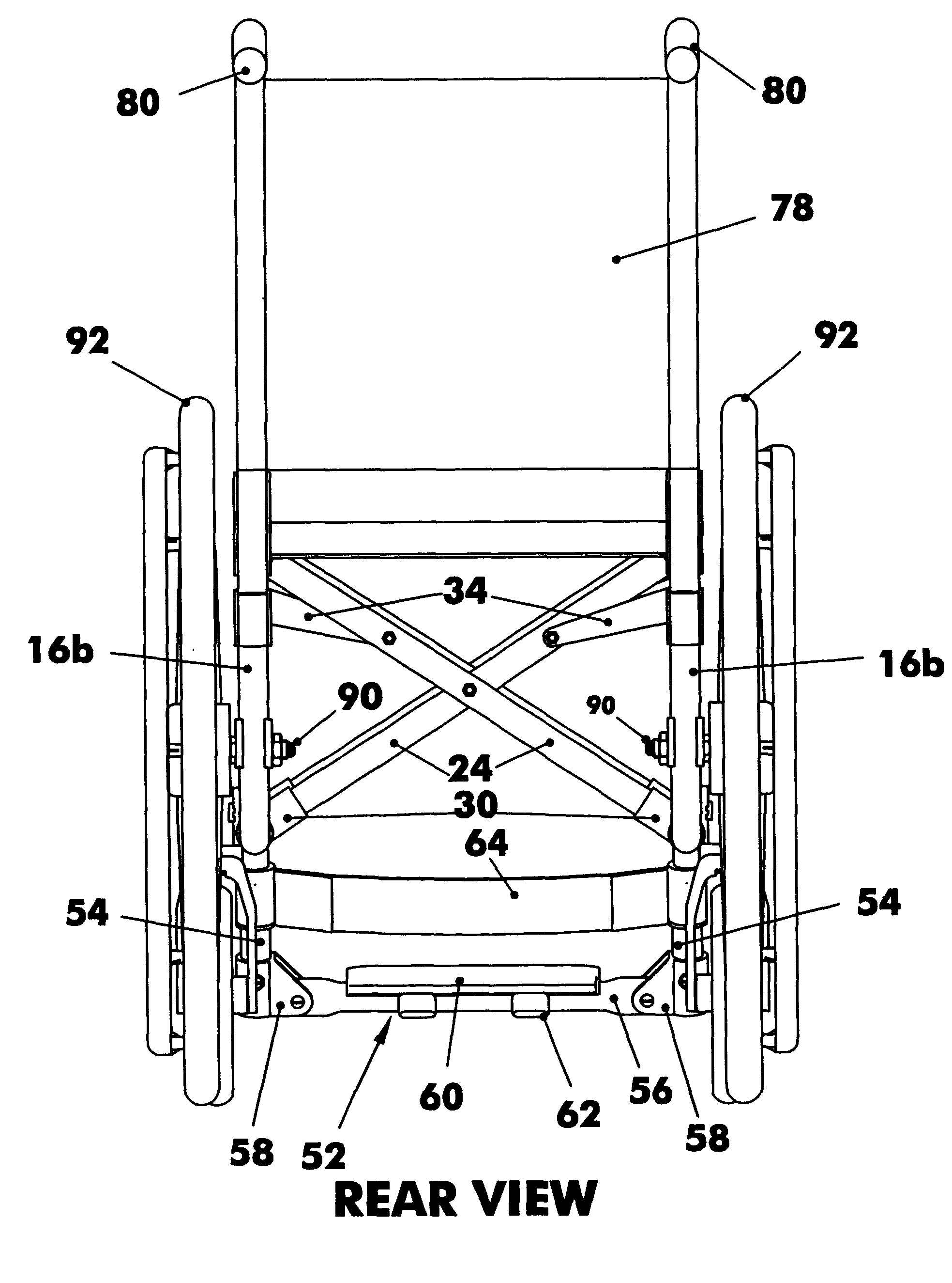
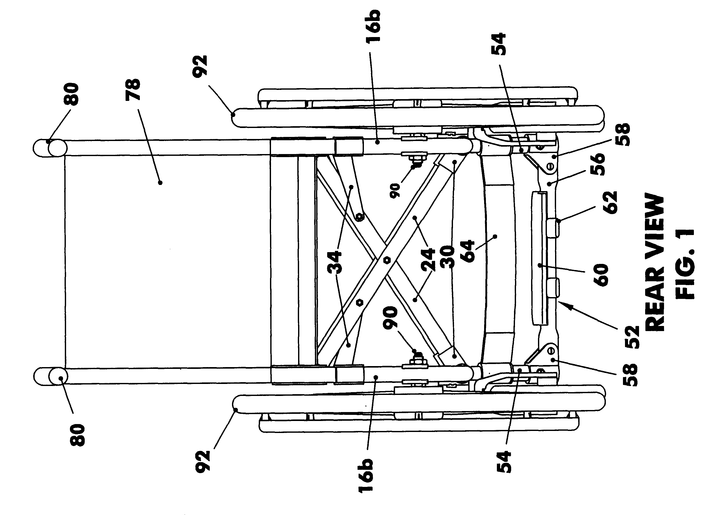
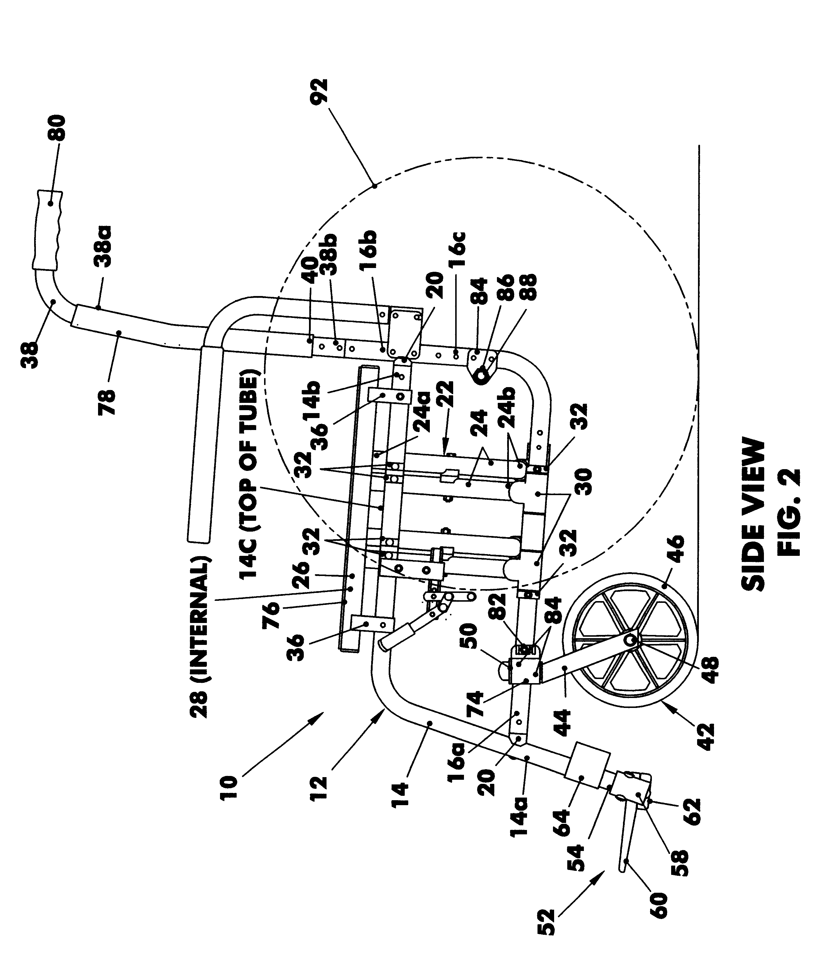
Referring now to the figures, in which identical or similar parts are designated by the same reference numerals throughout, and first referring to FIGS. 1, 2 and 3, a folding wheelchair in accordance with the present invention is generally designated by the reference numeral 10.

The chair 10 has a pair of like side frame assemblies 12 spaced from each other and including a generally horizontal top tube 14 and a generally horizontal bottom tube 16 below the top tube. The top and bottom tubes have front or distal ends 14a, 16a and rear or proximal ends 14b, 16b. Top and bottom tubes are joined at front ends 14a, 16a using connector fittings 20. The top tube 14 and the bottom tube 16 are secured to each other at front 14a, 16a and at the rear 14b, 16b using connector fittings 20. The top tube 14 has a row of holes 14c for seat attachment when converted to a rigid frame wheelchair.

The chair also has like crossbar assemblies 22 including an angular crossbar tube 24 and a generally horizon...


PUM


Abstract

A simple, durable, lightweight, economical wheelchair is disclosed that offers full convertibility from rigid frame to folding and vice versa, without sacrificing advantages of either design. In addition, it allows conversion to sports, companion, pediatric, front wheel drive, etc. as well as customizing to suit the end user's needs.

Description

1. Field of the InventionThe invention relates generally to wheelchairs and, more specifically, to convertible wheelchairs. All frame components are designed to accept parts for both the folding and rigid frame wheelchairs. Tubular components are designed to be easily attached to other members with the special connector fittings allowing for further conversion to other desirable designs.2. Description of the Prior ArtTwo different methods have been used in the design and production of manual wheelchairs. The most common is the folding cross brace wheelchair. This design utilizes a welded cross brace mechanism, allowing the wheelchair to fold similar to a director's chair (from side to side). The main advantage of this method is that the wheelchair can be easily folded by most users. The disadvantage of this design is low energy efficiency due to its loose construction since a part of the energy used to propel the wheelchair is transferred to the frame rather than the wheels.A second...

Claims


Application Information

Patent Timeline
Patent Type & Authority Patents(United States)
IPC IPC(8): A61G5/10A61G5/00A61G5/08A61G5/02A61G5/12
CPCA61G5/00A61G5/023A61G5/025A61G5/026A61G5/027A61G5/08A61G5/10A61G2005/0825A61G2005/1051A61G2005/128A61G5/0825A61G5/1051A61G5/128
Inventor FRIEDRICH, PAUL
Owner DA INT
Why Eureka
Try Eureka