Multitask processing unit

a multi-task processing and multi-task technology, applied in the field of microcomputers, can solve the problems of complex peripheral circuits of microcomputers, product size and more expensive, and the execution of instruction sequences

Inactive Publication Date: 2001-10-16
DENSO CORP
View PDF25 Cites 16 Cited by
  • Summary
  • Abstract
  • Description
  • Claims
  • Application Information

AI Technical Summary

Problems solved by technology

In addition, it is necessary to provide externally a runaway monitoring logic like a watchdog timer to monitor the runaway of program of each task, which contributes, combined with the above-mentioned matter, to making the peripheral circuits of a microcomputer complicated, leading to the product becoming larger-sized and more expensive.
Furthermore, in the conventional compositions, an erroneous jump to the address of other task and the execution of its instruction occurs due to an unexpected cause like noise.
In the past, a reset method employed in such a case has been to provide a runaway monitoring logic such as a watchdog timer in the peripheral circuits, which involves time loss before a runaway is detected since it has to be monitored externally, and a risk of the memory data or port data being destroyed in the meantime.
Furthermore, the pipeline processing in the conventional microcomputers has the problem of there occurring pipeline disturbances when a branch instruction is executed, causing at least one wasteful cycle, i.e. delayed cycle, thereby delaying the pipeline processing.
The cause of this wasteful cycle occurring after a branch instruction in the conventional pipeline processing is that if the branch instruction is fetched, the instruction address to be fetched next is predetermined in order beforehand regardless of the branch address, and the

Method used


Image

  • Multitask processing unit
  • Multitask processing unit
  • Multitask processing unit

Examples


Embodiment Construction

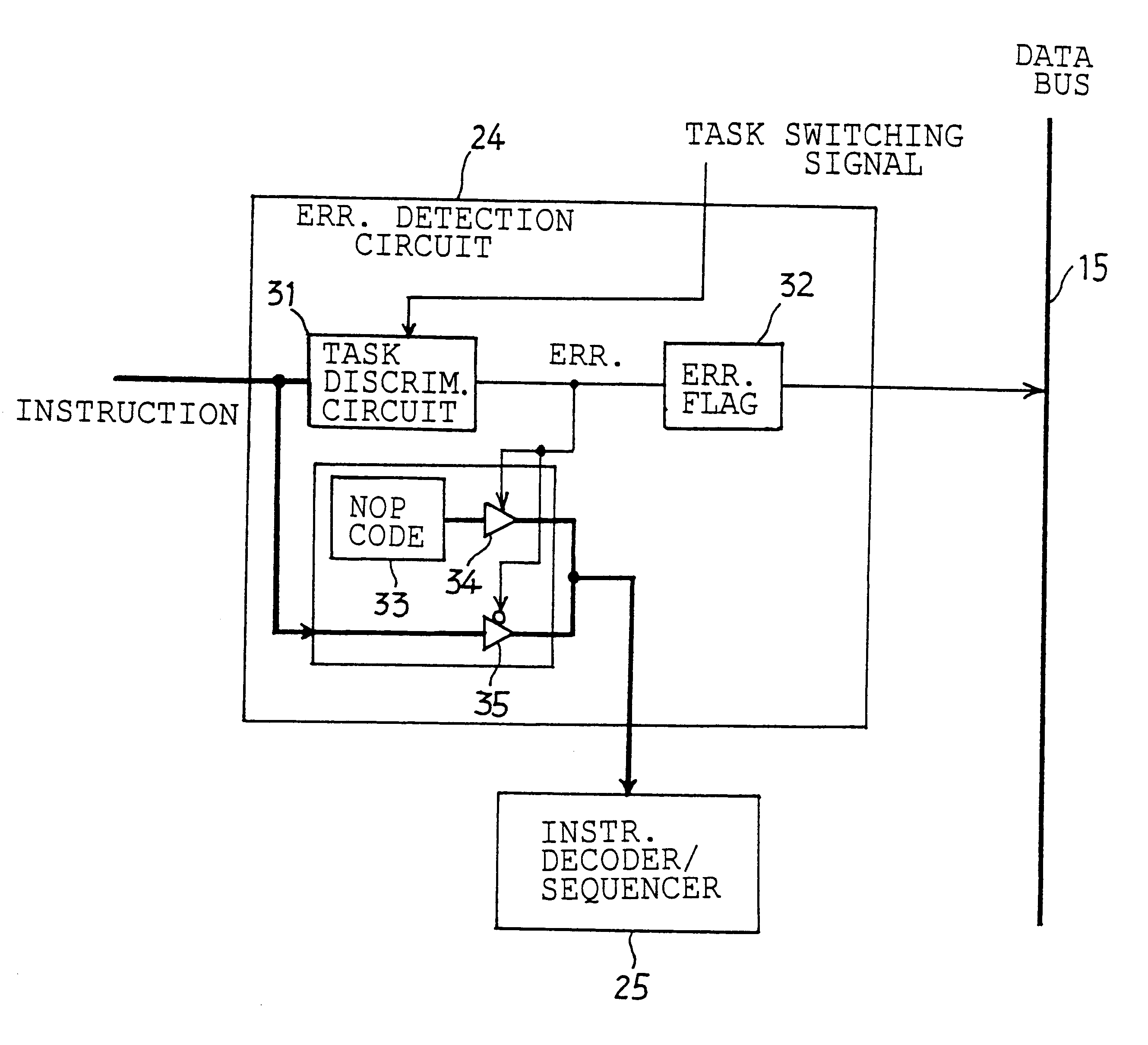
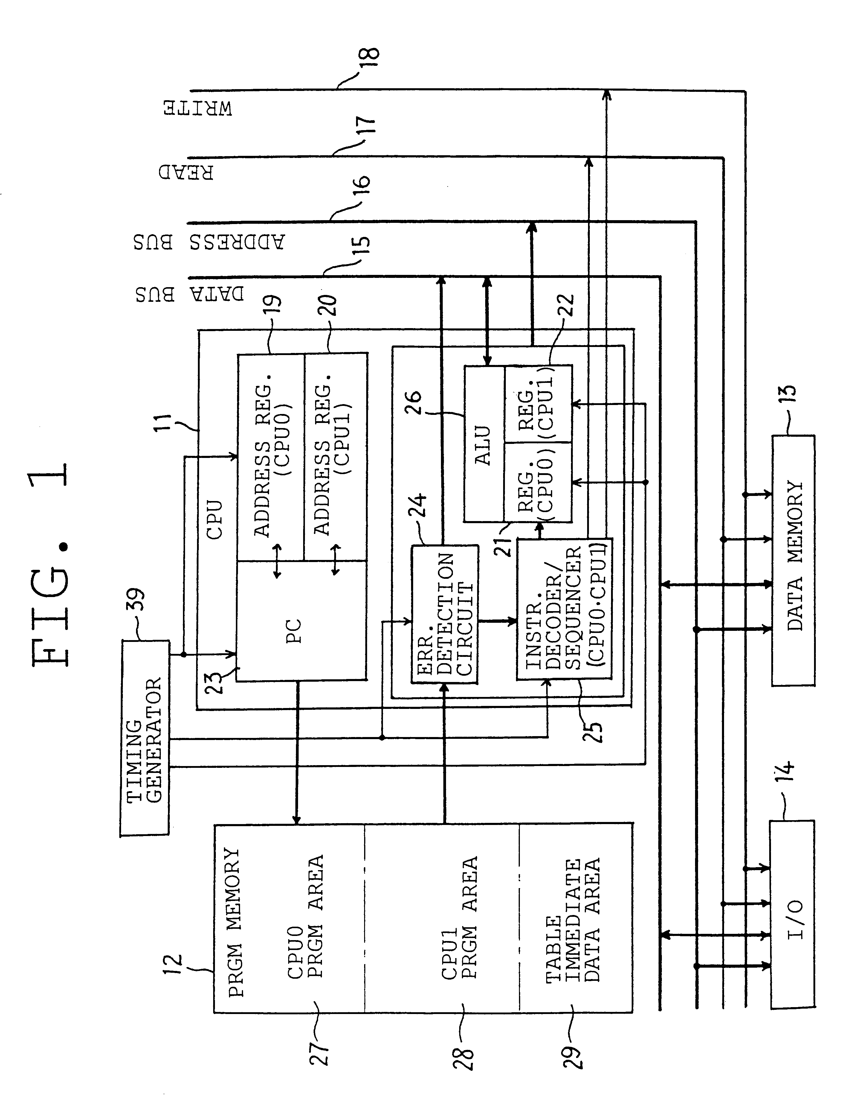
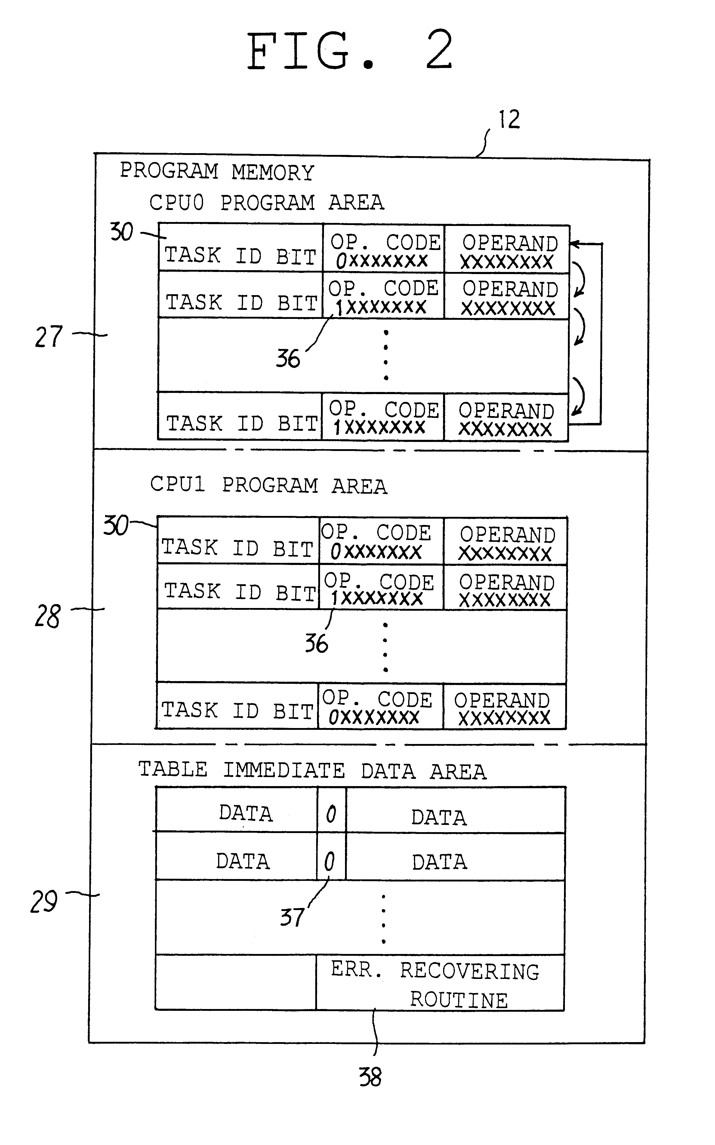
Described below is an embodiment of this invention referring to the drawings. The microcomputer in the embodiment is composed, for example, of a one-chip microcomputer, comprising CPU 11, program memory 12 consisting of ROM, data memory 13 consisting of RAM, I / O block 14 (input / output pin), timing generator 39 for generating a task switching signal (clock pulse) to be described later, data bus 15 for transmitting or receiving data, address bus 16 for transmitting or receiving address signal, and control bus 17 and 18 for transmitting or receiving read signal and write signal respectively.

For example, the CPU 11 is equipped with two address registers 19, 20 and two registers 21, 22 to perform a pipeline processing of two kinds of tasks (L-task and A-task) in parallel by time division. An alternate switch by the task switching signal from timing generator 39 of those address registers 19, 20 and registers 21, 22 will apparently actuate two CPU's by changing them over alternately. On t...


PUM


Abstract

The microcomputer shall be offered which has realized more simplified peripheral circuits and more reduced price, besides being provided with the functions of timer, runaway monitor and backup logic. To that effect, the address register and the register are installed which have two areas each in correspondence with two tasks (CPU0 and CPU1) to perform a pipeline processing of the two tasks in parallel and in time division by changing over alternately the two areas of the address register and the register by means of task switching signal. Then, while composing one task (L-task) with a fix-looped program for which a branch instruction is prohibited, the L-task is embedded with a routine to execute a runaway monitor and a timer operation for the other task (A-task). Furthermore, in case where anything abnormal is detected by L-task about the processing of A-task and it is reset, the L-task will execute a backup sequence to obtain a failsafe of the system.

Description

1. Field of the InventionThis invention relates to a microcomputer which is equipped with the function of time shared parallel processing of plural programs.2. Description of the Related ArtsSome of the recent microcomputers are designed to perform a time shared parallel processing of plural tasks by changing over the multi task processing in consecutive order by means of a register counter or a multiplexer as described, for instance, in the Japanease Patent Publication laid-open No. 58-155406, and No. 59-191654. In those conventional compositions, an exclusive hard timer is required to perform time processing by letting the elapsed time known when a task is executed. In addition, it is necessary to provide externally a runaway monitoring logic like a watchdog timer to monitor the runaway of program of each task, which contributes, combined with the above-mentioned matter, to making the peripheral circuits of a microcomputer complicated, leading to the product becoming larger-sized ...

Claims


Application Information

Patent Timeline
IPC IPC(8): G06F9/46G06F9/38G06F9/48
CPCG06F9/3842G06F9/3851G06F9/4843
Inventor ISHIHARA, HIDEAKIMAEDA, KOUICHI
Owner DENSO CORP
Why Eureka
Try Eureka