Door mechanism of automobile air conditioner

a technology of automobile air conditioner and door mechanism, which is applied in the direction of machine operation, vehicle cleaning, lighting and heating apparatus, etc., can solve the problems of complicated and high-cost construction, further limited small vehicle cabin space, and difficult control of the distribution of cooled air and warmed air

Inactive Publication Date: 2001-10-23
CALSONIC KANSEI CORP
View PDF17 Cites 40 Cited by
  • Summary
  • Abstract
  • Description
  • Claims
  • Application Information

AI Technical Summary

Problems solved by technology

Thus, when such device is mounted in a small car, the smaller vehicle cabin space is further limited, which is undesirable.
However, in the unit having the above-mentioned construction, the reduction in size of the door 105 tends to cause a difficulty with which distribution of cooled air and warmed air is controlled.
However, in this case, the addition of such auxiliary door causes a complicated and highly expensive construction, which is of course undesirable.
However, a door mechanism possessed by the above-mentioned vertically sliding type tends to have a higher resistance against air passage and thus tends to show weak points in operability.
When this air flow reduction occurs under a cooling condition of the air conditioner, the passengers can not get a satisfactorily cooled air.
However, if the clearance is too small, the sliding resistance of the door becomes increased causing a non-smoothed movement of the door 109.
While, if, for achieving a smoothed movement of the door, a larger clearance is provided between them, the undesired air leakage tends to occur.
When the door is applied with a certain wind pressure, noises caused by the play tend to be produced, which are transmitted to the vehicle cabin to make passengers uncomfortable.
Furthermore, the presence of the mode doors causes a marked increase in air flow resistance and production of noises.
Thus, stable mixing between the cooled air and warmed air is not achieved and thus stable air temperature controlling becomes difficult.
However, in case wherein the air temperature controlling rib is employed, it is difficult to determine the size of the temperature controlling rib and the positioning of the same.
Furthermore, due to employment of the temperature controlling rib, the number of parts increases and thus assembling work of the case becomes difficult or at least troublesome, and cost is increased.
Furthermore, even when the air temperature controlling rib is so positioned and sized as to exhibit the best ventilation mode, it often occurs that the air temperature controlling rib has a bad effect on the temperature controlling in the other mode (viz., the mode other than the ventilation mode, wherein the ventilation door 107 is closed and another door is opened).
Although the above-mentioned example is an example applied to the defrosting mode, similar drawbacks tend to appear in case of the ventilation mode and / or the foot mode.
However, in the above-mentioned air conditioning device, the side ventilation openings are formed in the right and left side portions of the center ventilation opening, that is, in a limited space positioned above the upper wall of the case.
Since, in this arrangement, the ventilation door for opening and closing the center ventilation opening is used for controlling the air distribution, tuning of the air flow amount is difficult.
Thus, even the device employs the gear type sliding mechanism, undesired phenomena, such as gear slippage and the like, do not occur and thus smoothed operation is expected.
When, in all of these positions, it is needed to support a laterally middle portion of the door proper, a dead space is inevitably produced at a portion where the laterally middle portion of the door proper is supported.
However, even when the mix door takes the middle position, undesired play of the door does not occur and thus a desired control becomes possible.
Furthermore, due to disuse of the temperature no controlling rib and the simplification of the door operating mechanism, advantages in cost are obtained.
Furthermore, since the door proper is slid along the cam grooves, undesired play of the door proper does not occur even when the door proper is applied with a wind pressure.
Thus, even the device employs the gear type sliding mechanism, undesired phenomena, such as gear slippage and the like, do not occur and thus smoothed operation is expected.
Furthermore, since the door proper is slid along the cam grooves, undesired play of the door proper does not occur even when the door proper is applied with a wind pressure.
Furthermore, undesired reduction in air amount blown to the vehicle cabin, which would be caused by the air flow resistance by the defroster door, does not occur.

Method used


Image

  • Door mechanism of automobile air conditioner
  • Door mechanism of automobile air conditioner
  • Door mechanism of automobile air conditioner

Examples


embodiment-1

[Embodiment-1]

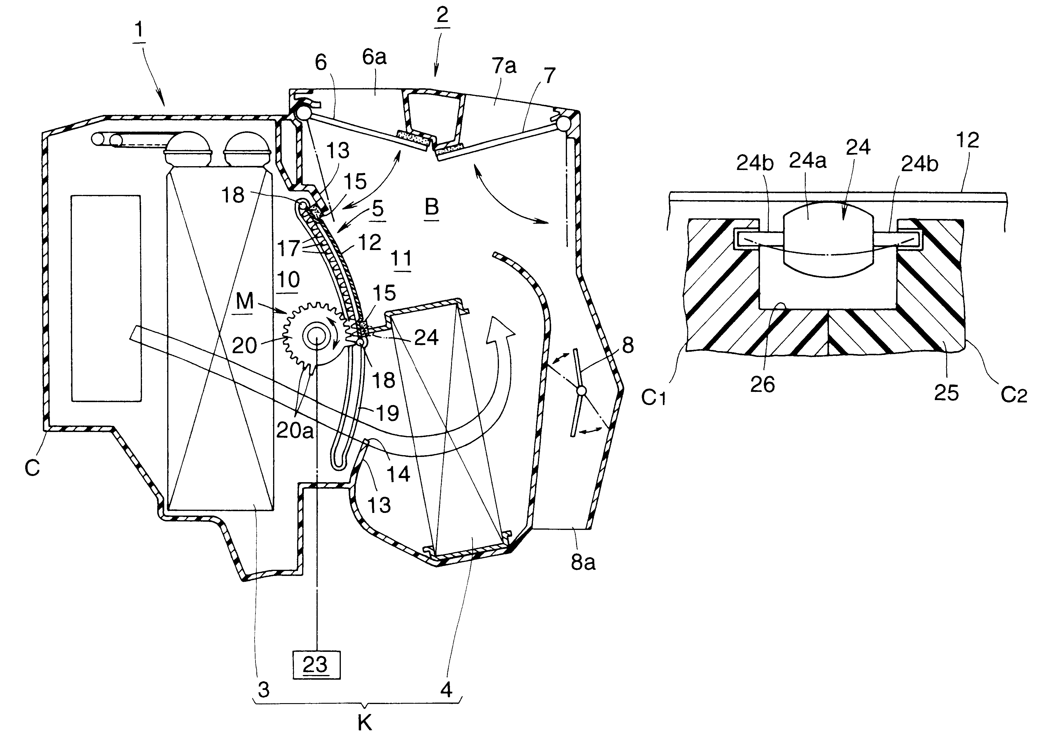
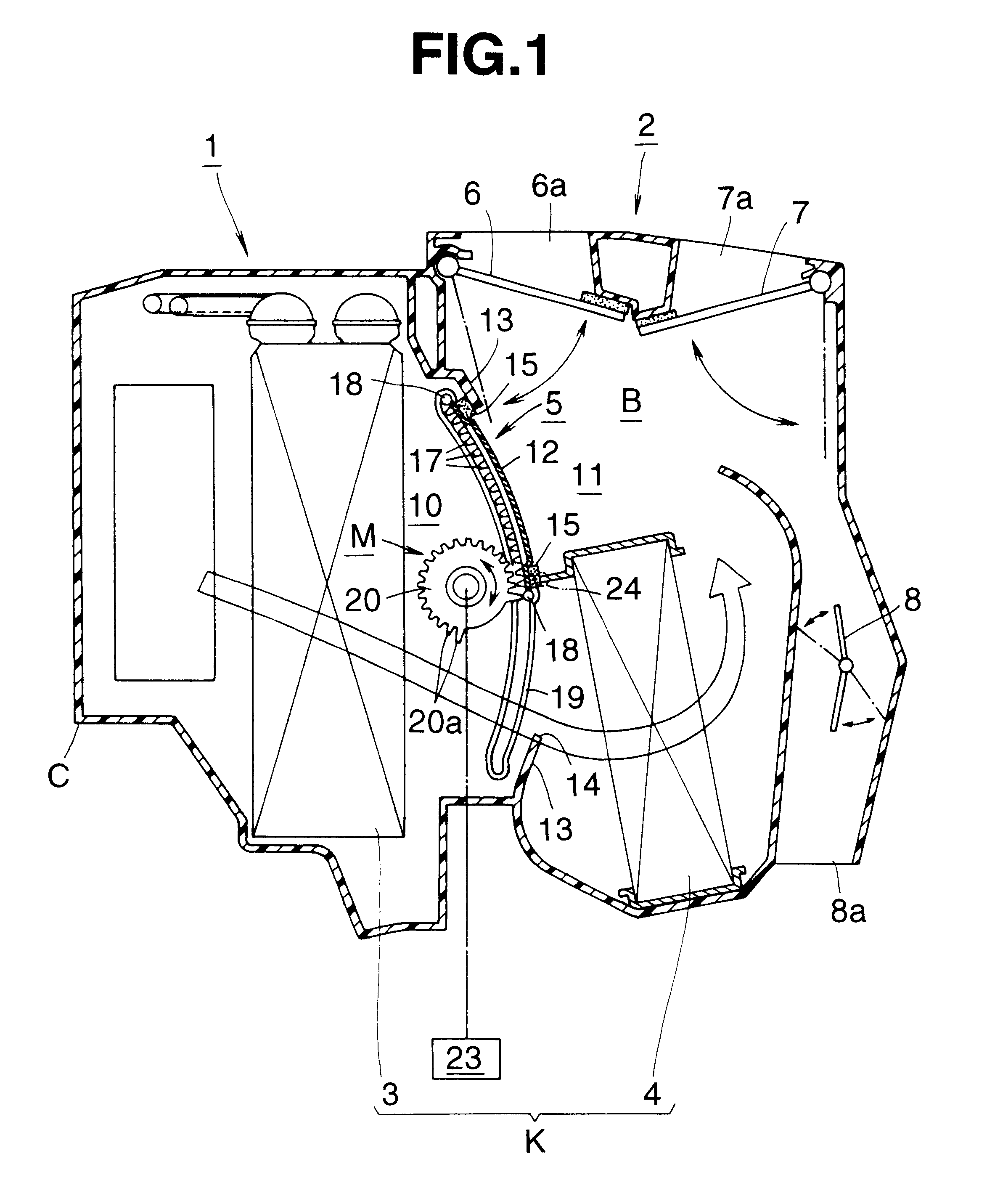
FIG. 1 is a drawing showing an automotive air conditioning device which is an embodiment of the present invention, which is a sectional view taken along the line 1--1 of FIG. 2. FIG. 2 is a plan view of FIG. 1, FIG. 3 is a horizontally sectional view of a door mechanism, FIG. 4 is a partially cut perspective view of a door, FIG. 5 is an end view taken along the line 5--5 of FIG. 3, FIG. 6 is an enlarged illustration showing an essential portion of the door, FIG. 7 is an illustration showing a cam groove portion, and FIG. 8 is an illustration of a supporting roller, which is a sectional view taken along the line 8--8 of FIG. 7.

As is shown in FIG. 1, a door mechanism of an automotive air conditioning device of the embodiment is applied to a mix door.

As is shown in FIG. 1, the automotive air conditioning device is equipped with a case C which comprises a cooler unit 1 and a heater unit 2 which are united in such a manner as to reduce a longitudinal length "L" (see FIG. 16...

first embodiment

In this full-cool mode, a much amount of cooled air is forced to impinge against the door proper 12, which causes such a tendency that the door proper 12, which has a relatively long width, becomes deformed or flexed in a downstream direction. However, since, in this first embodiment, the laterally middle portion of the door proper 12 is resiliently supported by the supporting roller 24, undesired deformation of the door proper 12 is prevented even when a marked wind pressure is applied to the door proper 12. Furthermore, due to the same reason, smoothed operation of the door is achieved without suffering from undesired gear slippage, and lowering in the temperature controlling performance, which would be caused by the deformation of the door proper 12, does not occur. Furthermore, even if the door proper 12 is somewhat deformed under the influence of heat produced by the evaporator 3 and the heater core 4 which are positioned near the door proper, the deformation of the door proper...

embodiment-2

[Embodiment-2]

The automotive air conditioning device of this embodiment comprises, as is seen from FIG. 10, a unit case "C" which has a short longitudinal length "L" and includes a cooler unit 1 and a heater unit 2 which are united and aligned in a fore-and-aft direction of the associated motor vehicle.

Within the unit case C, there are installed an evaporator 3 which produces a cooled air by cooling air introduced thereto, a heater core 4 which produces a warmed air by heating the cooled air, a mixing chamber 31 which mixes the cooled air and the warmed air to produce a temperature-controlled air, a hoot duct 8d which is defined by both the mixing chamber 31 and a swelled inside wall 30, a defroster opening 6a and a ventilation-foot opening 40 which are arranged at an extension line of the inside wall 30, and a door mechanism which functions to control the cooled air and warmed air.

The door mechanism comprises a slide type mix door 5 which is arranged between the evaporator 3 and th...


PUM


Abstract

A mix door (5) is arranged in air passages (10, 11) of an automotive air conditioning device. The mix door (5) is arranged to extend in a direction to shut an air flow blown from the upstream air passage (10) and swelled in a downstream direction with a predetermined radius of curvature. The door (5) is guided by arcuate cam grooves (19) and driven upward and downward to achieve open / close operation with the aid of a sliding mechanism (M). Compact construction, reduction in air flow resistance, smoothed handling, high sealing and high temperature controlling are achieved.

Description

The present invention relates to a door mechanism of an automotive air conditioning device, which can slide in a limited space to smoothly control an air flow.TECHNICAL BACKGROUNDIn general, an automotive air conditioning device comprises an intake unit for introducing outside and inside air, a cooler unit for cooling the introduced air and a heater unit for heating the introduced air, these three units being combined in series and installed in a limited space of a vehicle cabin, such as a space defined below an instrument panel.However, due to the in-line connection of the three units, the automotive air conditioning device is compelled to have an enlarged size. Thus, when such device is mounted in a small car, the smaller vehicle cabin space is further limited, which is undesirable.In view of the above, as is shown in FIG. 16, there has been proposed a device in which a cooler unit 101 and a heater unit 102 are positioned close to each other and aligned along a fore-and-aft direct...

Claims


Application Information

Patent Timeline
Patent Type & Authority Patents(United States)
IPC IPC(8): B60H1/00
CPCB60H1/0005B60H1/00692B60H1/00857Y10T137/87812B60H1/00
Inventor TSURUSHIMA, AKIHIROYOSHIDA, TOSHIYUKIONDA, MASAHARUUCHIDA, TOSHIYAKOSHIDA, KATSUAKIKUROKAWA, KATSUHIRO
Owner CALSONIC KANSEI CORP
Why Eureka
Try Eureka