Method for continuously controlling color of display device

Inactive Publication Date: 2001-10-30
TEXAS DIGITAL SYST
View PDF42 Cites 137 Cited by
  • Summary
  • Abstract
  • Description
  • Claims
  • Application Information

AI Technical Summary

Problems solved by technology

Since the first transistor cannot be simultaneously turned ON and OFF, it w

Method used


Image

  • Method for continuously controlling color of display device
  • Method for continuously controlling color of display device
  • Method for continuously controlling color of display device

Examples


Embodiment Construction

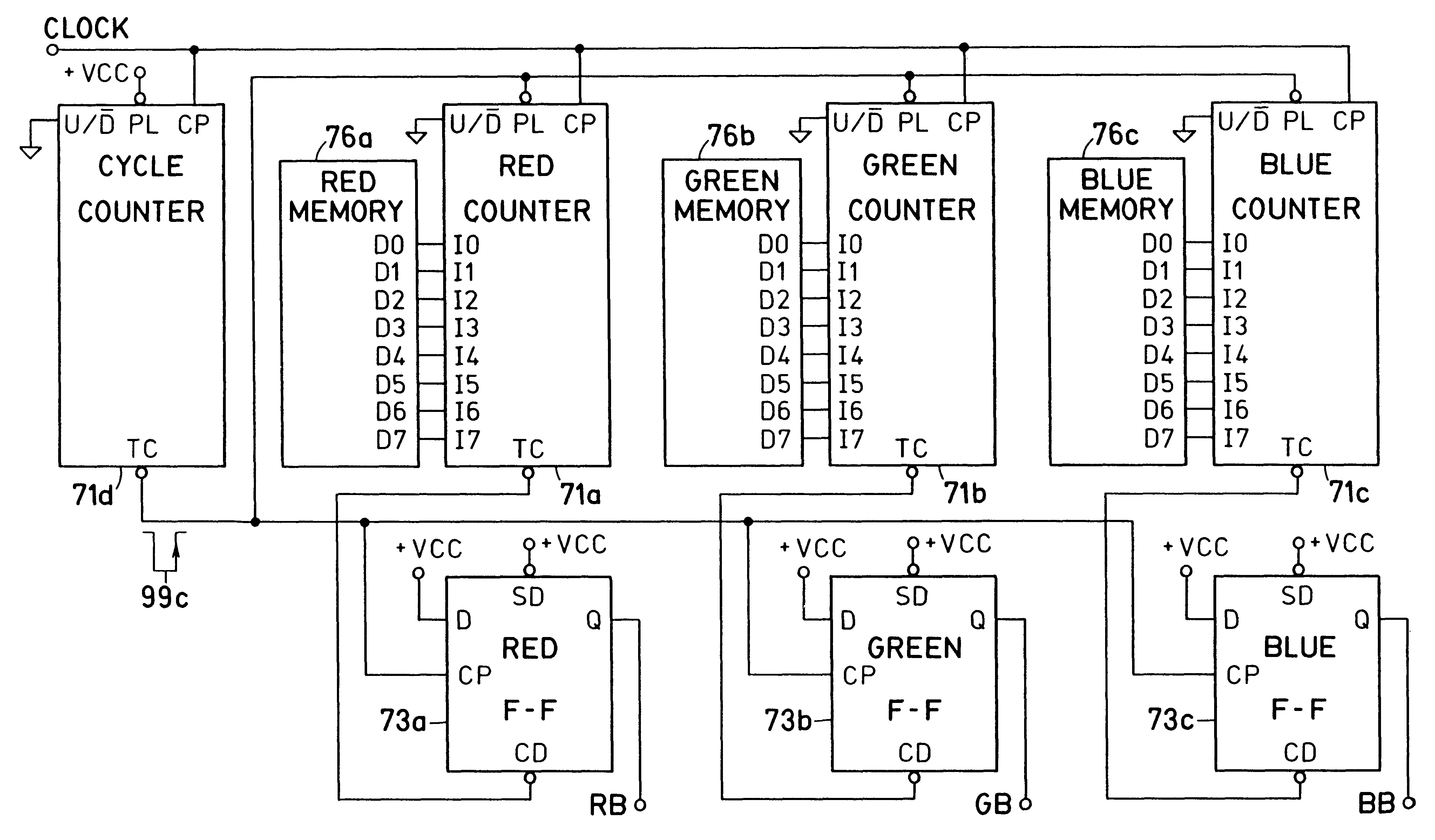
2 considers the memory data `02` (HEX) to generate light of substantially green color. At the beginning of the counter cycle, data `02` are loaded into counter 71f, and, simultaneously, flip-flop 73 is set. The counter 71f will count down and will reach zero count after 2 clock cycles. At that instant it produces at its output TC a negative pulse 99e to reset flip-flop 73. It is readily apparent that flip-flop 73 was set for 2 clock cycles, or about 1% of the time, and reset for 254 clock cycles, or about 99% of the time. Accordingly, red bus 5 of display element 42 is energized for about 1% of the time, and green bus 6 is energized for the remaining about 99% of the time. As a result, display element 42 illuminates in substantially green color.

The EXAMPLE 3 considers the memory data `80` (HEX) to generate light of substantially yellow color. At the beginning of the counter cycle, data `80` are loaded into counter 71f, and, simultaneously, flip-flop 73 is set. The counter 71f will c...


PUM


Abstract

A method for continuously controlling color of a display device comprises the steps of receiving three sets of data respectively representing the portions of three primary colors, accumulating three counts in accordance with the data, respectively, and setting three bistable devices for the respective durations of the accumulating. The outputs of the three bistable devices are coupled for respectively energizing three buses, to which the light emitting diodes of three primary colors are connected in accordance with their colors, for controlling the portions of the light signals of the primary colors emitted therefrom.

Description

1. Field of the InventionThis invention relates to a method for continuously controlling the color of a display device.2. Description of the Prior ArtA display device described in U.S. Pat. No. 3,740,570, issued on Jun. 19, 1973 to George R. Kaelin et al., uses special LEDs that exhibit different colors when subjected to different currents. The LEDs are biased by pulses of different amplitudes, to achieve different colors of the display, and by the length inversely proportional to the pulse amplitude, to compensate for variable brightness of the display caused by different amplitudes of the pulses.A circuit employing a dual-color LED driven by a dual timer is described in the article by Bill Wagner entitled 2-color LED+driver=versatile visual effects, published on Oct. 2, 1980 in EDN volume 25, No. 19, page 164. Since dual-color LEDs are connected to conduct currents in opposite directions, it would be impossible to forwardly bias them simultaneously.An electronic display having seg...

Claims


Application Information

Patent Timeline
IPC IPC(8): G01R13/22G01R13/40G01R13/26G01R15/00G01R13/00G01R15/12G09G3/14G09G3/04G01R13/02
CPCG01R13/26G01R13/405G01R15/125G09G3/14G01R13/02
Inventor HAVEL, KAREL
Owner TEXAS DIGITAL SYST
Why Eureka
Try Eureka