Dual blade hair clipper

a hair clipper and dual-blade technology, applied in the direction of metal working devices, etc., can solve problems such as breaking the stylist's concentration

Inactive Publication Date: 2001-11-13
HILLEBRANDT DANIEL J
View PDF11 Cites 39 Cited by
  • Summary
  • Abstract
  • Description
  • Claims
  • Application Information

AI Technical Summary

Problems solved by technology

The hairstylist is, therefore, required to switch back and forth between two separate clipper devices which

Method used


Image

  • Dual blade hair clipper
  • Dual blade hair clipper
  • Dual blade hair clipper

Examples


Embodiment Construction

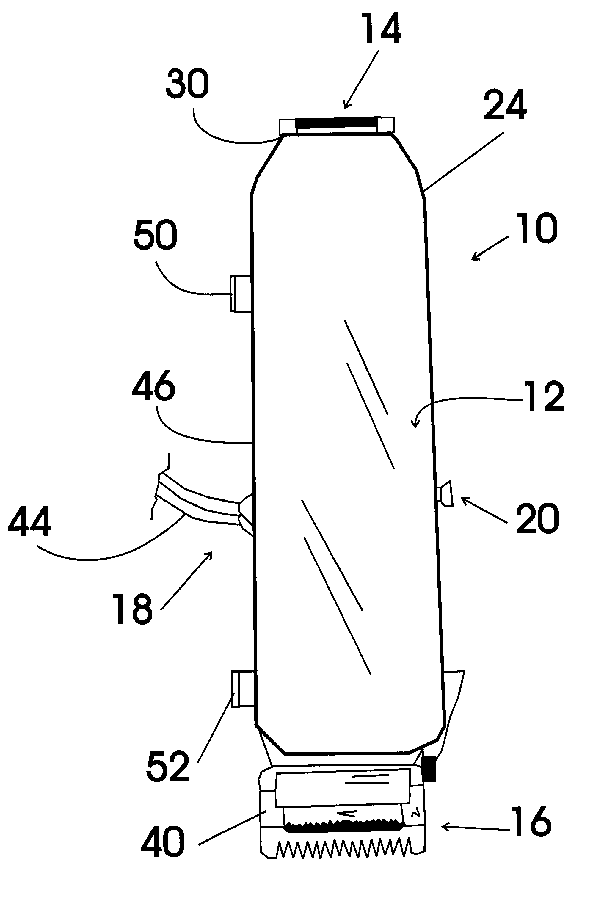
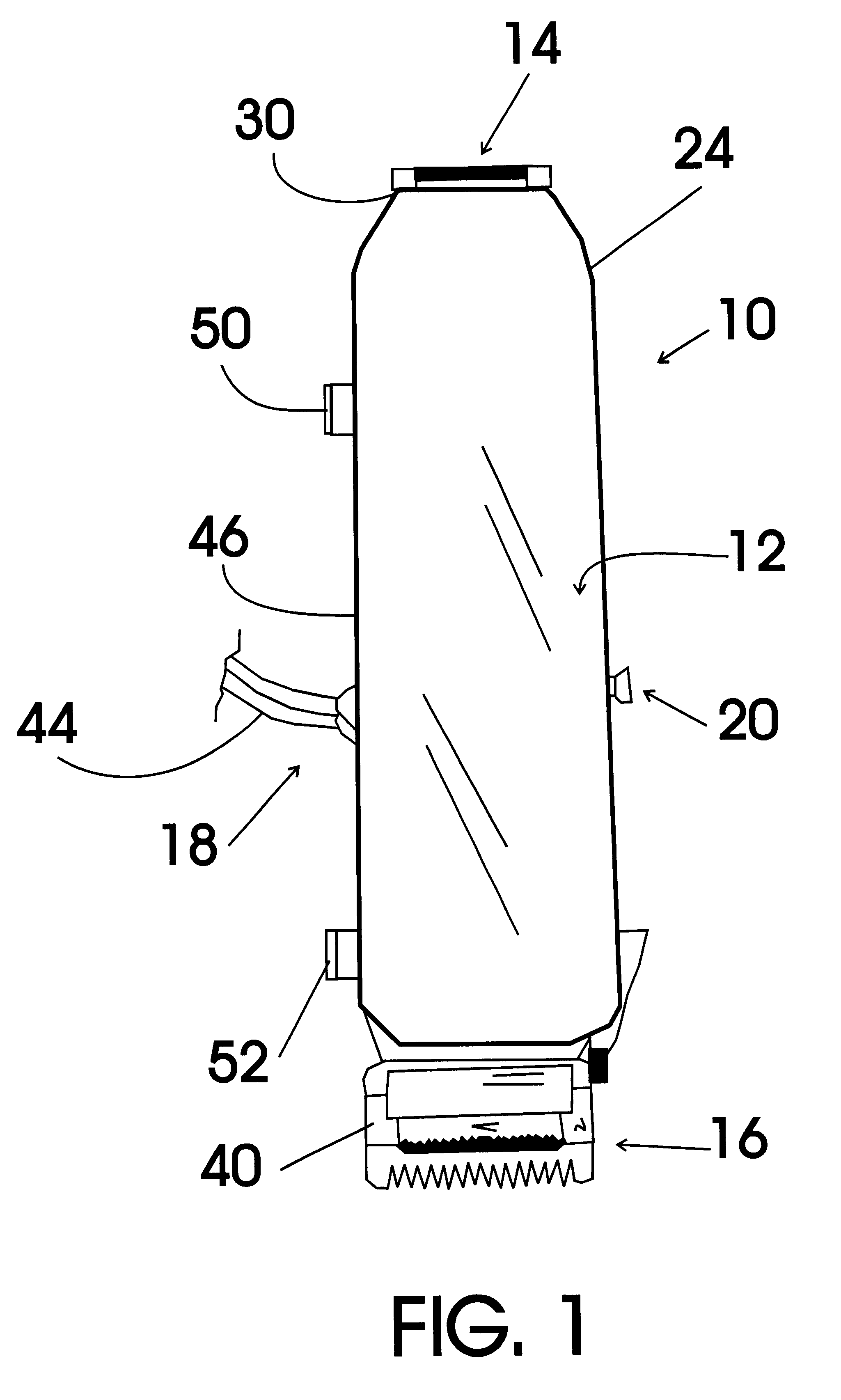
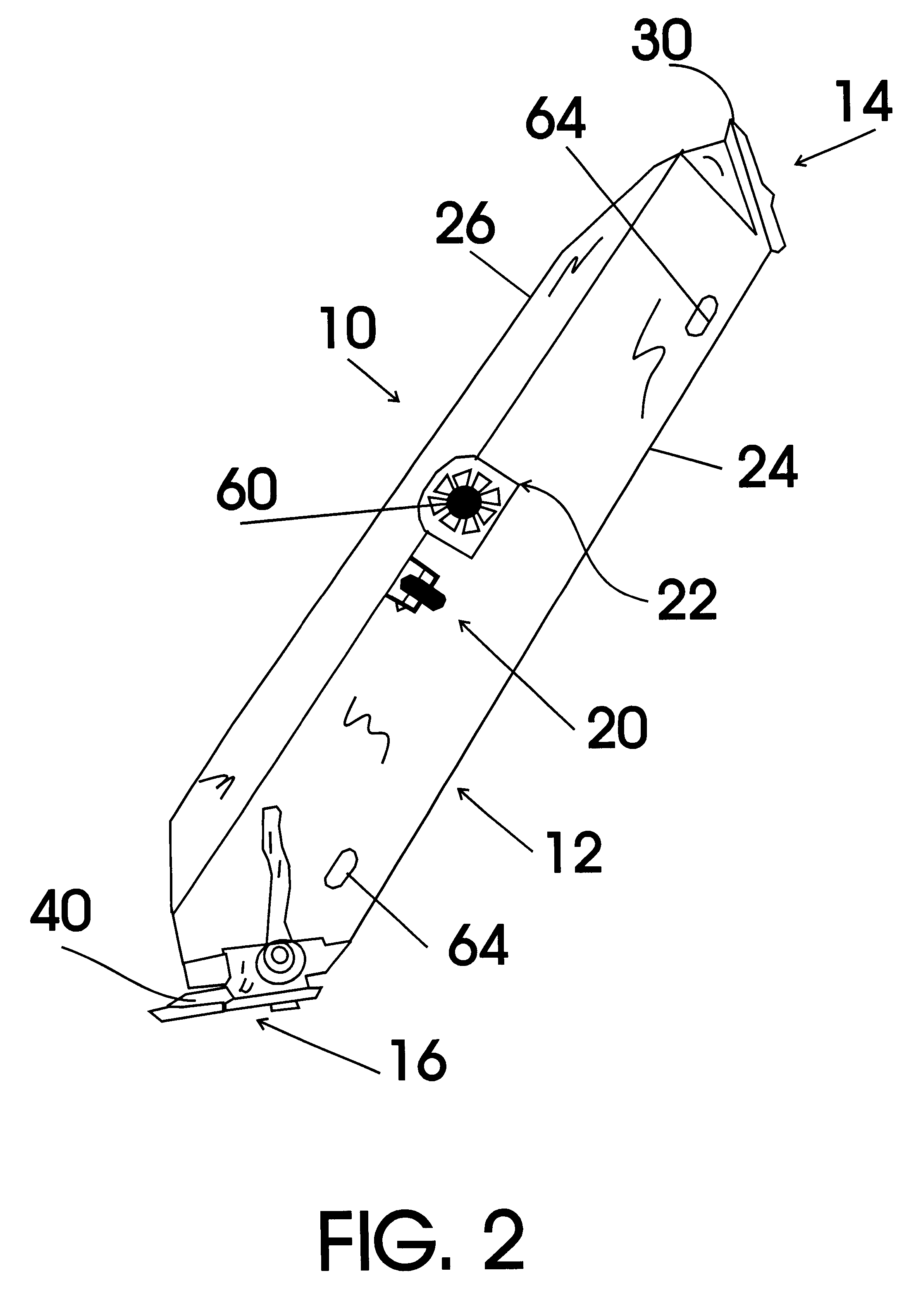
FIGS. 1-4 illustrate an exemplary embodiment of the dual blade hair clipper system of the present invention, generally designated 10. With reference to FIGS. 1-3, dual blade hair clipper system 10 includes a two-piece, molded plastic, motor housing, generally designated 12; an independently powered edger unit, generally designated 14; an independently powered taper unit, generally designated 16; a power cord directing assembly, generally designated 18; a three-position on / off switch, generally designated 20; and a motor cooling system, generally designated 22.

Motor housing 12 includes a top section 24 and a bottom section 26 that are sized to provide a handle graspable by a hand of a user. Referring now also to FIG. 4, independently powered edger unit 14 includes a ten Watt, edger unit drive motor 28 housed within motor housing 12 and an edger blade assembly 30, powered by edger unit drive motor 28, provided at one end 32 of motor housing 12. Independently powered taper unit 16 incl...


PUM


Abstract

A hair clipper unit that includes edger blades on one end and taper blades on the other end. The clipper system allows a stylist to rapidly switch operation between the two sets of clipper blades and includes a power cord directing assembly including a power cord that extends from a center side surface of a motor housing and a cord securing clip on either side of the cord housing exit point for holding the cord in the proper orientation during use. The dual blade clipper unit also includes two separate drive motors, one for each set of clipping blades, and a drive motor cooling system to further reduce the heat generated by operation of the clipper unit.

Description

The present invention relates to grooming devices and more particularly to a dual blade hair clipper system that includes a motor housing, an independently powered edger unit, an independently powered taper unit, a power cord directing assembly, a three-position on / off switch, and a motor cooling system; the motor housing being sized to provide a handle graspable by a hand of a user; the independently powered edger unit including an edger unit drive motor housed within the motor housing and an edger blade assembly, powered by the edger unit drive motor, provided at one end of the motor housing; the independently powered taper unit including a taper unit drive motor housed within the motor housing and an adjustable taper blade assembly, powered by the taper unit drive motor, provided at an opposite end of the motor housing; the power cord directing assembly including a power cord extending out from a side surface of the motor housing midway between the edger blade assembly and the ta...

Claims


Application Information

Patent Timeline
IPC IPC(8): B26B19/04B26B19/10
CPCB26B19/10
Inventor HILLEBRANDT, DANIEL J.
Owner HILLEBRANDT DANIEL J
Why Eureka
Try Eureka