
Electrode-lead coupling skull mounted port assembly

a technology of lead coupling and skull, which is applied in the direction of head electrodes, internal electrodes, therapy, etc., can solve the problems of reducing or eliminating the effectiveness of treatment, unfavorable treatment effect, and difficult manipulation

Inactive Publication Date: 2001-11-27
ELECTRO CORE TECH
View PDF6 Cites 100 Cited by
  • Summary
  • Abstract
  • Description
  • Claims
  • Application Information

AI Technical Summary

Problems solved by technology

The effects of the field generated by the electrical contacts is highly position dependent, and as a result, movement of the electrode after proper positioning can reduce or eliminate all effectiveness of the treatment.
If external portions of the lead are not secured, subsequent manipulations of the electrode leads can cause this unwanted movement.
The use of a suture to secure the electrode, even indirectly, is a considerable drawback as it is difficult to manipulate, not easily reversible, and does not provide a readily obvious means for ensuring that the lead is truly secured against movements when the external portion is manipulated during the remainder of the surgery.
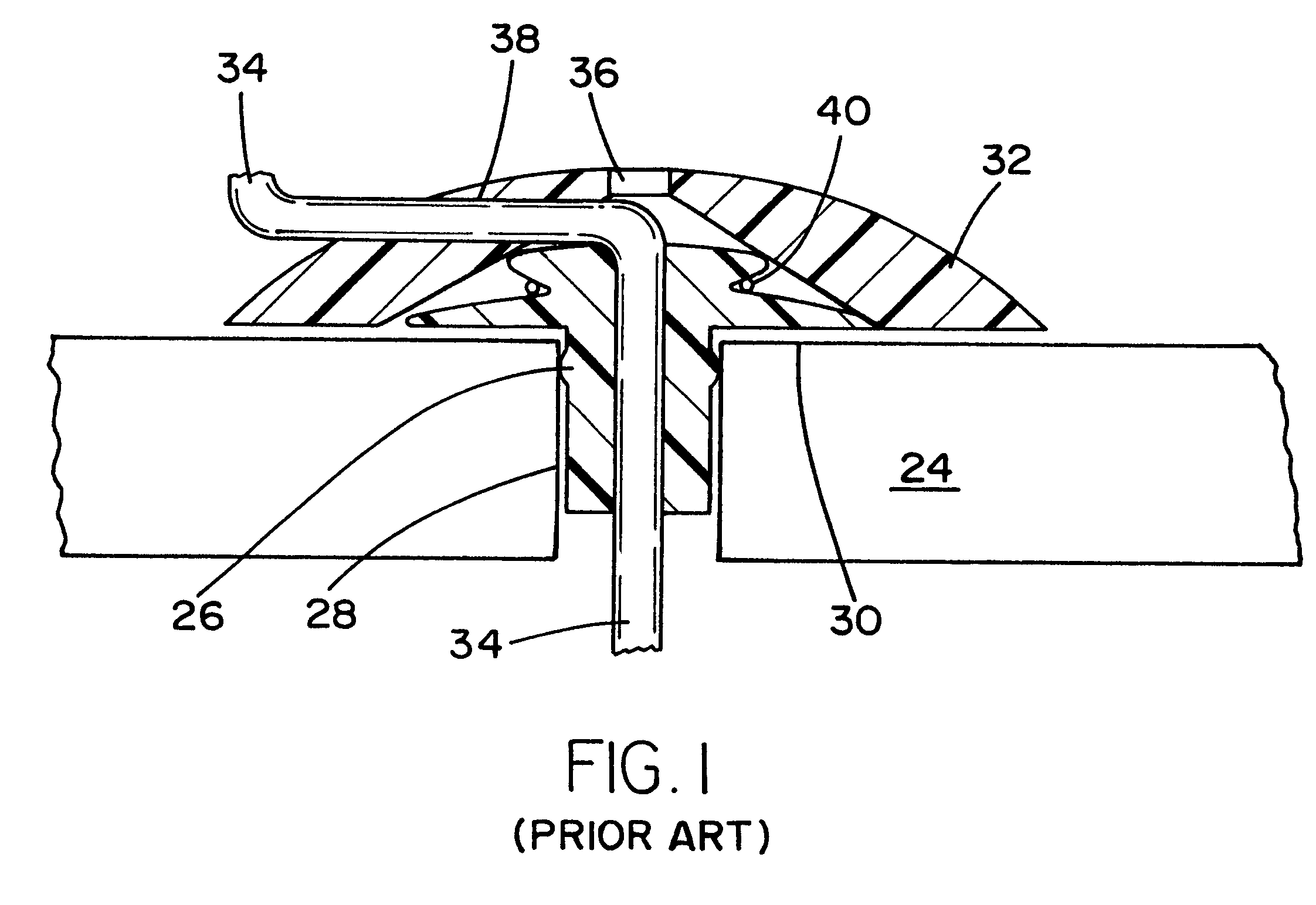
Also, the compression lock, as in the first example is not easily viewed as it happens under the cap member.
Unfortunately, because of the techniques and equipment used in implantation of the lead within the brain, the joining of the proximal end of the electrode to the extending cable occurs after the distal end of the electrode has been fully implanted and positioned, and the cannula has been removed.
The presently available extension cables and the coupling means for connecting the proximal end of the lead thereto are prone to causing damage to the proximal end of the implanted electrode.

Method used


Image

  • Electrode-lead coupling skull mounted port assembly
  • Electrode-lead coupling skull mounted port assembly
  • Electrode-lead coupling skull mounted port assembly

Examples


Embodiment Construction

While the present invention will be described more fully hereinafter with reference to the accompanying drawings, in which particular embodiments are shown, and with respect to methods of implantation, it is to be understood at the outset that persons skilled in the art may modify the invention herein described while achieving the functions and results of this invention. Accordingly, the descriptions which follow are to be understood as illustrative and exemplary of specific structures, aspects and features within the broad scope of the present invention and not as limiting of such broad scope. Like numbers refer to similar features of like elements throughout.

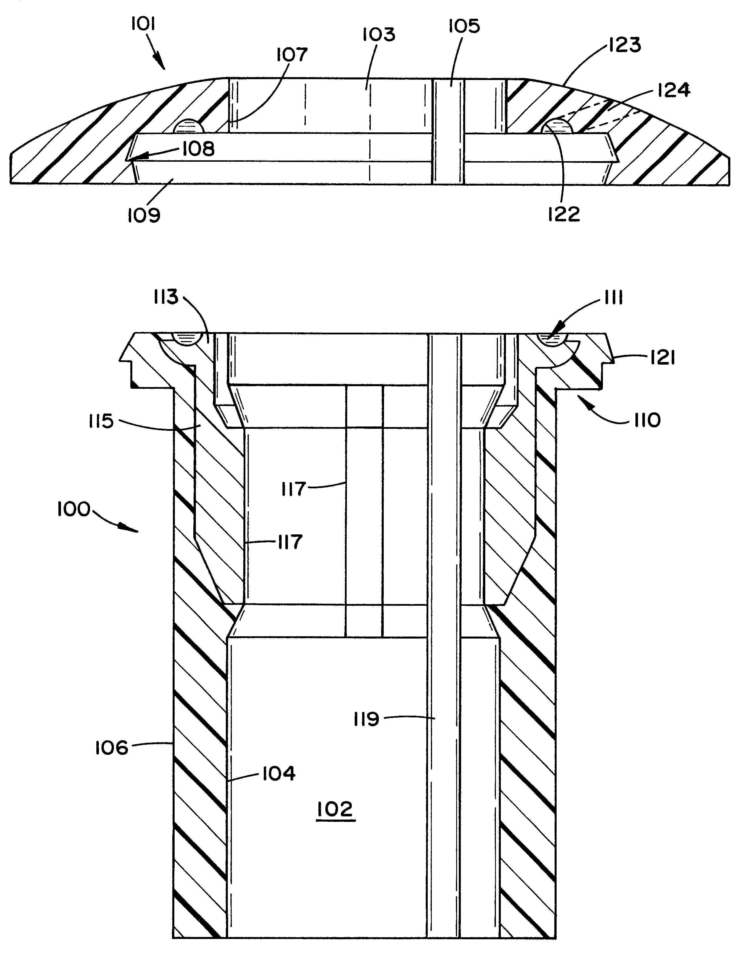
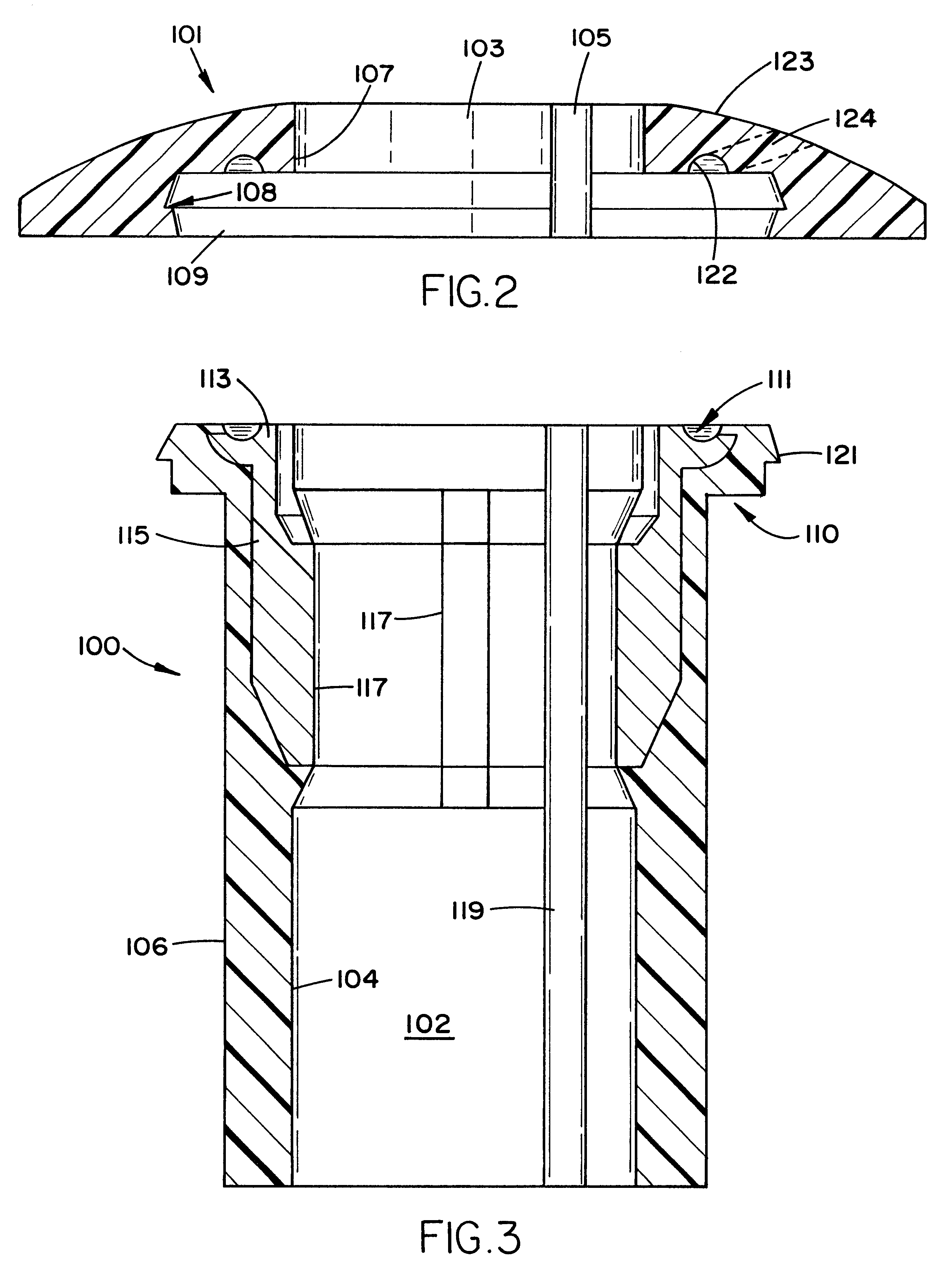
Referring now to FIGS. 2 and 3, the present invention comprises a cylindrical skull port member 100 which is designed to securely fit within the burr hole formed in a patient's skull, through which the surgeon implants the active tip of the electrode lead, and a cap member 101 which seats on the upper portion of the port membe...


PUM


Abstract

An assembly for securing an electrode lead within a burr hole formed in a patient's skull and couples it to a coupling lead which extends to a remote signal generator. The securing assembly has three separate components. The first is a bone port which seats within a preformed burr hole in the skull. The bone port is a cylindrical shaped short tube with central axial hole having electrical contacts formed on the inner surface. These electrical contacts are connected to corresponding contacts in a circumferential groove formed in the upper surface of the port for receiving the proximal end of the stimulation electrode. The second component is a docking element which seats in the port. The docking element has corresponding electrical contacts on the exterior surface thereof, which connect to terminal pads in an axial bore formed therein. The coupling lead is inserted into the bore and is thereby connected to the stimulation electrode by virtue of the contacts made between the port and the docking element. A cap element seats over the port and docking elements, holding them together and securing the stimulation electrode in the assembly.

Description

1. Field of the InventionThis invention relates generally to a device used in the interventional treatment of neurological disorders, and more particularly to a novel electrode-lead coupling assembly which mounts to a burr hole in a patient's skull and couples an implanted electrode to a lead which extends external to the skull to a powered signal generator.2. Description of the Prior ArtThe use of electrical stimulation of the brain for the purposes of alleviating pain and the treatment of other neurological afflictions has been utilized for a number of years, and in many instances has become the standard of care. The traditional technique comprises the implantation of a long flexible electrical lead through a burr hole in the patient's skull, and into electrical contact with the pathological section of the patient's brain. The flexible lead comprises a plurality of long helically wound wires encased in a elastomeric sheath. The distal end of the wire lead include electrical contac...

Claims


Application Information

Patent Timeline
IPC IPC(8): A61N1/05
CPCA61N1/0534A61N1/0539
Inventor ERRICO, JOSEPH P.
Owner ELECTRO CORE TECH
Learn More