Automatic scanner calibration

a scanner and automatic technology, applied in the direction of electrographic process, digital output to print units, instruments, etc., can solve the problems of large amount of labor required to complete repetitive scans, many scanning and printing technologies are complex, and the quality of light produced by light sources is drifting

Inactive Publication Date: 2001-12-04
ELECTRONICS FOR IMAGING
View PDF21 Cites 91 Cited by
  • Summary
  • Abstract
  • Description
  • Claims
  • Application Information

AI Technical Summary

Problems solved by technology

Many scanning and printing technologies are complex and, due to many different physical and environmental factors, may drift in their color response For example, in the case, of a scanner; the quality of light produced by the light source drifts over time due to the gradual variation of both el

Method used


Image

  • Automatic scanner calibration
  • Automatic scanner calibration
  • Automatic scanner calibration

Examples


Embodiment Construction

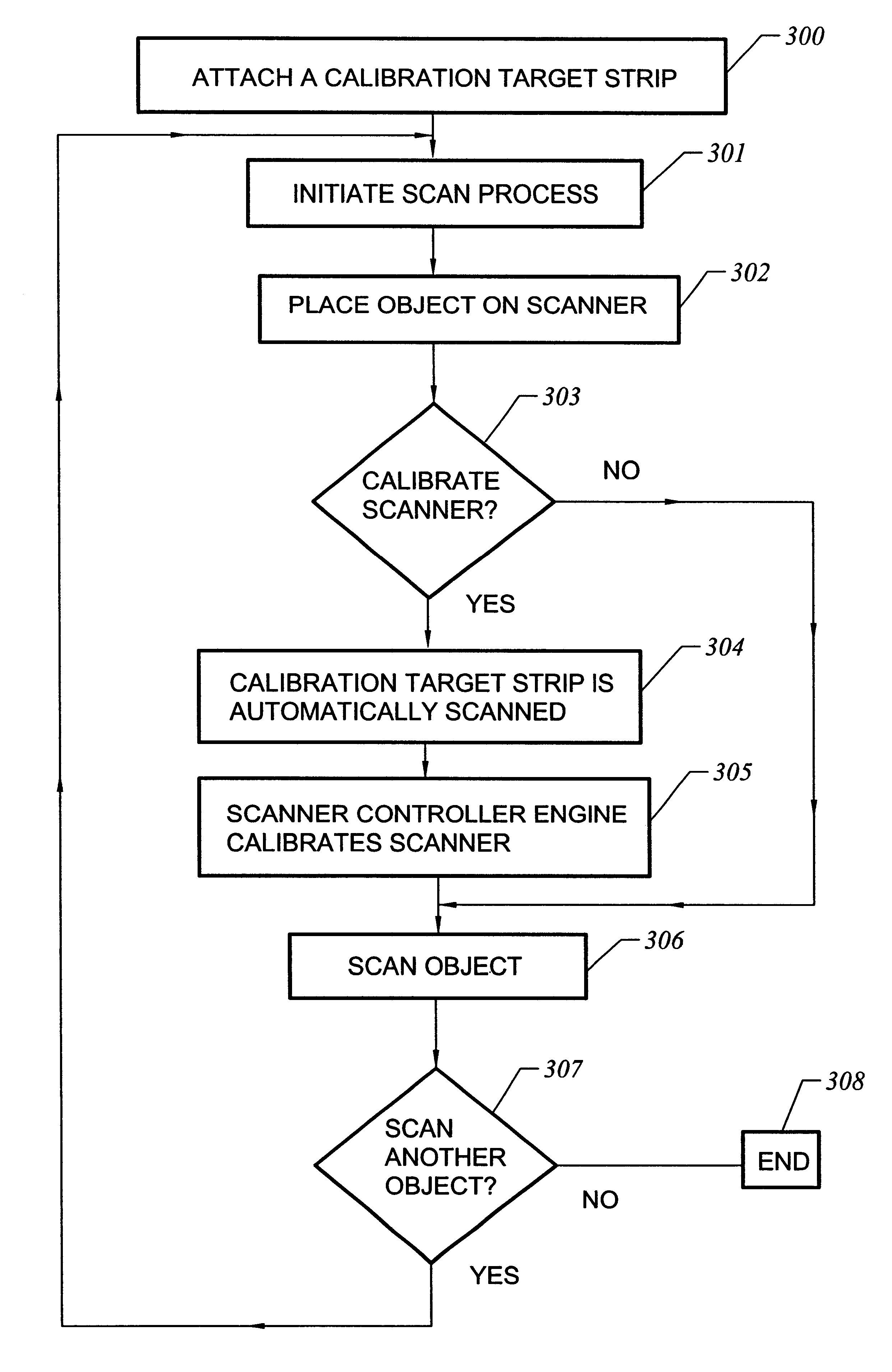
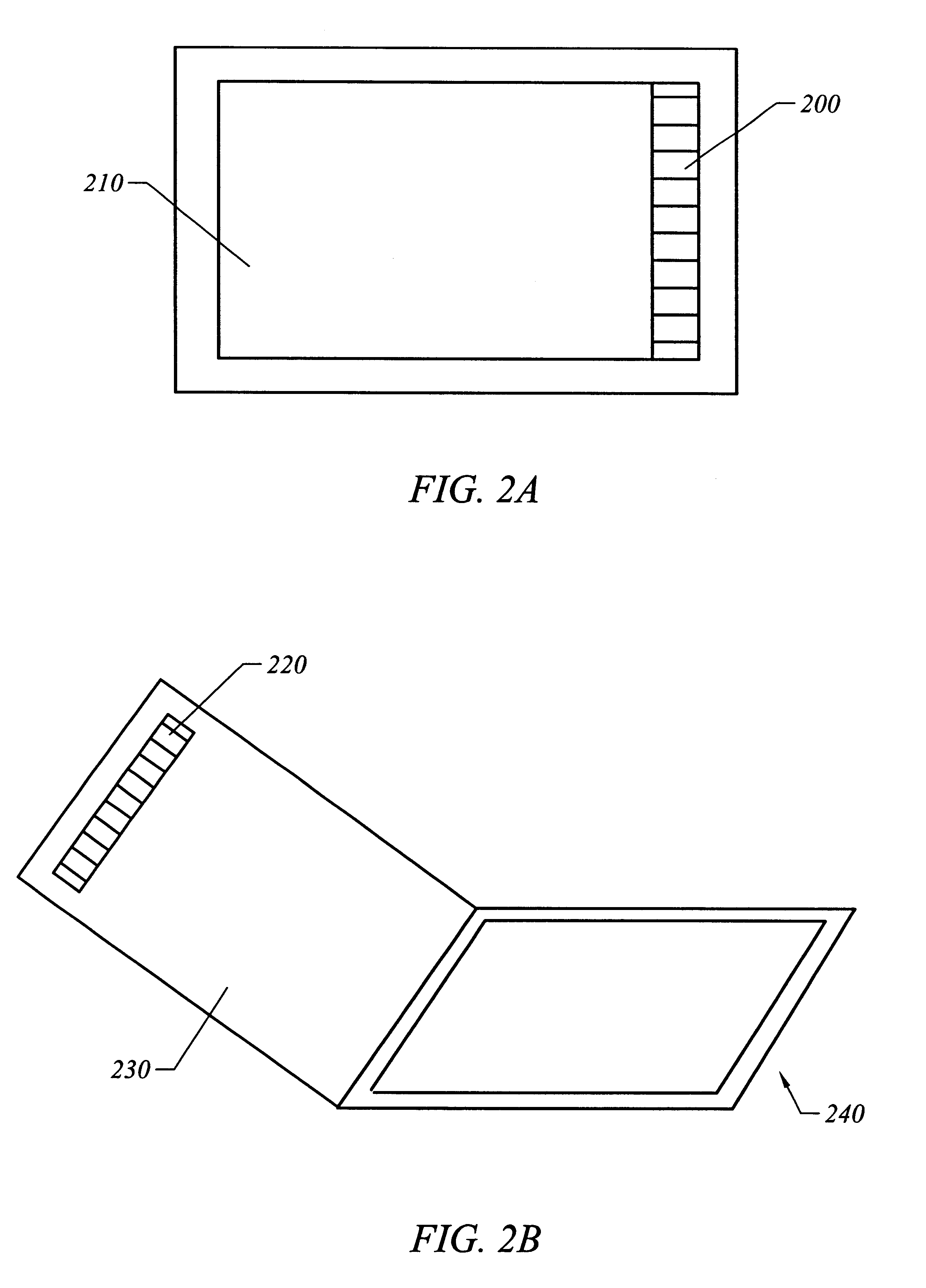
This invention provides an automatic scanner calibration method and apparatus which includes a calibration target strip that, in the presently preferred embodiment of the invention, a user attaches once to any of an inside surface of a scanner glass, an outside surface of a scanner glass, or an inside of a scanner cover. During a normal scan of an object, the user can select to ignore the calibration target strip or can select to scan the calibration target strip. If the calibration target strip is scanned, then the scanner is calibrated automatically during the scan of the object.

In the preferred embodiment of the invention, the calibrated target strip generally is about one-quarter of an inch to one-half of an inch wide and generally has length that is approximately equal to the length or the width of the platen of the scanner. Standard manufactured calibration target strips can be purchased and used in the invention.

The strip also can be customized to suit a combination of needs....


PUM


Abstract

An automatic scanner calibration method and apparatus is disclosed in which a calibrated target, such as a Kodak(R) gray strip, is attached to a scanning surface of a scanner. The target is thin and has a width or length of platen of a scanner. During a normal scan, the calibration target area can be ignored or scanned depending on user selection. If the strip is scanned, then the resulting information is used to calibrate the scanner automatically. Such calibration is more accurate than an older in time or preset default calibration Another embodiment of the invention actuates a print of a printer calibration target on a printer on a scheduled basis. Thereafter, the user can take the printer calibration target and place it on the scanner and perform a calibration of a scanner/printer system.

Description

1. Field of the InventionThe invention relates to the calibration of a scanner. More particularly, the invention relates to a method and apparatus for automatically calibrating a scanner. Another embodiment of the invention relates to calibrating a printer automatically.2. Description of the Prior ArtMany scanning and printing technologies are complex and, due to many different physical and environmental factors, may drift in their color response For example, in the case, of a scanner; the quality of light produced by the light source drifts over time due to the gradual variation of both electronic and optical components of the scanner. In the case of a printer, the amount of color toner or ink that is printed on paper changes over time. It is preferable that printers and scanners have a steady and consistent color response.Prior art systems attempt to compensate for the difference in color behavior between a measured response of the printer or scanner and an ideal response of the p...

Claims


Application Information

Patent Timeline
IPC IPC(8): H04N1/60
CPCH04N1/00002H04N1/00013H04N1/00031H04N1/00045H04N1/0005H04N1/00055H04N1/00063H04N1/00068H04N1/00087H04N1/0009H04N1/6033
Inventor MOTAMED, MARGARET
Owner ELECTRONICS FOR IMAGING
Why Eureka
Try Eureka