
Magnetic recording medium, magnetic recording and reproducing apparatus, and manufacturing method of magnetic recording medium

a technology of magnetic recording and recording medium, which is applied in the manufacture of head surfaces, conductive pattern formation, instruments, etc., can solve the problems of damage or deformation affecting the flying performance of the magnetic head, and achieve the effect of good flying performance and high reliability

Inactive Publication Date: 2006-08-17
TDK CORPARATION
View PDF7 Cites 32 Cited by
  • Summary
  • Abstract
  • Description
  • Claims
  • Application Information

AI Technical Summary

Benefits of technology

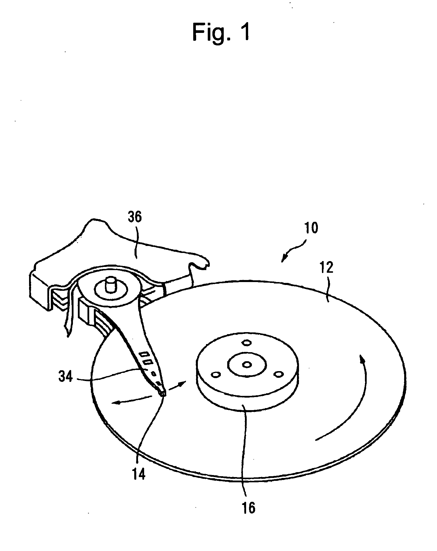
[0011] In view of the foregoing problems, various exemplary embodiments of this invention provide a magnetic recording medium in which a recording layer is formed in a concavo-convex pattern and recording elements are formed as convex portions of the concavo-convex pattern, provides a good flying performance of a magnetic head, and has high reliability, a magnetic recording and reproducing apparatus including that magnetic recording medium, and a manufacturing method of that magnetic recording medium.
[0016] Moreover, static electricity can be easily generated in a magnetic recording medium in which a concave portions between recording elements are filled with filling elements, because the filling elements have a large electric resistivity. Thus, foreign matter such as dust can easily adhere to a surface of the magnetic recording medium. Such foreign matter is also considered as one factor affecting the flying performance of the magnetic head.
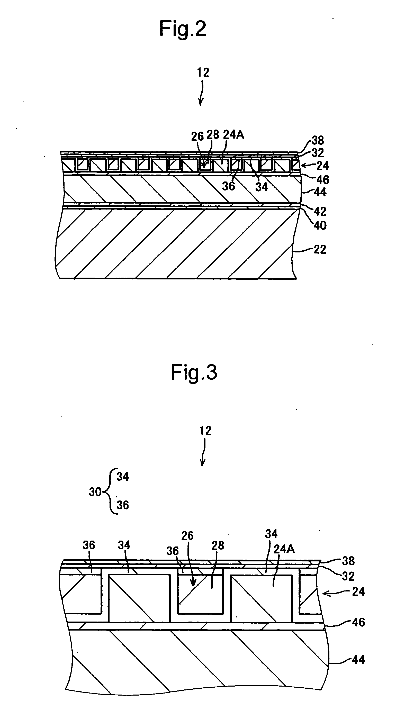
[0017] In order to overcome that problem, the conductive film having a smaller electric resistivity than the filling elements is formed over the filling elements. Thus, it is considered that generation of static electricity can be suppressed and degradation of the flying performance of the magnetic head caused by foreign matter such as dust can be suppressed.
[0018] In addition, when a continuous conductive film is formed from a single material on both the recording elements and the filling elements, the effect of suppressing the variation of the bias voltage during formation of the protective layer can be largely enhanced. In this case, it is expected that the effect of suppressing formation of polymer-like amorphous carbon be obtained even when the electric resistivity of the conductive film is equal to or larger than that of the filling element.
[0034] According to the present invention, it is possible to realize a magnetic recording medium that includes a recording layer formed in a concavo-convex pattern in which recording elements are formed as convex portions, provides a good flying performance of a magnetic head, and has high reliability, and a magnetic recording and reproducing apparatus including that magnetic recording medium.

Problems solved by technology

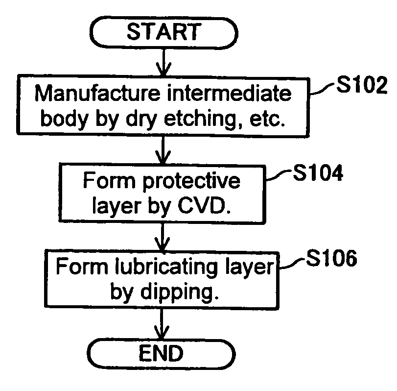
As a result, the inventors found that, when a protective layer of carbon was formed over the recording elements and the filling elements, amorphous carbon which had a polymer-like molecular structure and low hardness and which was not compact was formed in a part of the protective layer in some cases and intermittent contact of the magnetic head with that part caused a damage or deformation affecting the flying performance of the magnetic head.

Method used


Image

  • Magnetic recording medium, magnetic recording and reproducing apparatus, and manufacturing method of magnetic recording medium
  • Magnetic recording medium, magnetic recording and reproducing apparatus, and manufacturing method of magnetic recording medium
  • Magnetic recording medium, magnetic recording and reproducing apparatus, and manufacturing method of magnetic recording medium

Examples


working example 1

[0109] The magnetic recording medium 12 was manufactured in the manner described in the first exemplary embodiment. The structure of a main part of the manufactured magnetic recording medium 12 is described below.

[0110] The substrate 22 had a diameter of approximately 65 mm and was formed of glass. The recording layer 24 had a thickness of approximately 18 nm and was formed of a CoCrPt alloy. In the data region, a width of the recording element 24A in the radial direction was 100 nm and a width of the concave portion 26 in the radial direction was 100 nm too. A depth of the concave portion 26 was 18 nm.

[0111] The first conductive film 34 had a thickness of approximately 1 nm and was formed of W. The filling element 28 was formed of SiO2. The second conductive film 36 had a thickness of approximately 2 nm and was formed of Ta.

[0112] The protective layer 32 had a thickness of approximately 3 nm and was formed of DLC. The lubricating layer 38 had a thickness of approximately 1.5 nm ...

working example 2

[0121] The magnetic recording medium 80 was manufactured in the manner described in the fourth exemplary embodiment. The configuration of the substrate 22, the recording layer 24, the filling element 28, the protective layer 32, and the lubricating layer 38 was the same as that in Working Example 1.

[0122] The conductive film 82 had a thickness of approximately 1 nm and was formed of Ta.

[0123] A specific method for depositing the filling material and the conductive film 82 was briefly described.

[0124] First, the filling material was deposited on the recording layer 24 having a concavo-convex pattern by bias sputtering to have a thickness of approximately 80 nm. In this deposition, the deposition power (i.e., the power applied to target) was set to approximately 500 W, the bias power (i.e., the power applied to the substrate 22) was set to approximately 250 W, the flow rate of Ar gas was set to approximately 50 sccm, and the pressure inside the vacuum chamber was set to approximate...

working example 3

[0129] The magnetic recording medium 90 was manufactured in the manner described in the fifth exemplary embodiment. The structure of the substrate 22, the recording layer 24, the filling elements 28, the second conductive film 36, the protective layer 32, and the lubricating layer 38 were the same as that in Working Example 1.

[0130] A specific method for depositing the filling material and the second conductive film 36 is briefly described.

[0131] First, the filling material was deposited on the recording layer 24 having a concavo-convex pattern by bias sputtering to have a thickness of approximately 16 nm. In this deposition, the deposition power (i.e., the power applied to target) was set to approximately 500 W, the bias power (i.e., the power applied to the substrate 22) was set to approximately 250 W, the flow rate of Ar gas was set to approximately 50 sccm, and the pressure inside the chamber was set to approximately 0.3 Pa.

[0132] The second conductive film 36 was then deposi...


PUM

PropertyMeasurementUnit
thicknessaaaaaaaaaa
thicknessaaaaaaaaaa
thicknessaaaaaaaaaa

Abstract

A magnetic recording medium is provided which includes a recording layer formed in a concavo-convex pattern including recording elements formed as convex portions, provides a good flying performance of a magnetic head, and has high reliability. A magnetic recording and reproducing apparatus including that magnetic recording medium and a manufacturing method of that magnetic recording medium are also provided. The magnetic recording medium includes: the recording layer formed in a predetermined concavo-convex pattern over a substrate, the recording elements being formed as convex portions of the concavo-convex pattern; filling elements with which concave portions between the recording elements are filled; a conductive film which has a smaller electric resistivity than the filling elements and is formed over the filling elements; and a protective layer which covers the recording elements and the filling elements and is in contact with an upper surface of the conductive film.

Description

BACKGROUND OF THE INVENTION [0001] 1. Field of the Invention [0002] The present invention relates to a magnetic recording medium in which a recording layer is formed in a predetermined concavo-convex pattern and recording elements are formed as convex portions of the concavo-convex pattern, a magnetic recording and reproducing apparatus including that magnetic recording medium, and a manufacturing method of that magnetic recording medium. [0003] 2. Description of the Related Art [0004] Conventionally, a protective layer is formed over a recording layer in a magnetic recording medium such as a hard disk in order to protect the recording layer against contact with a magnetic head or the like. The protective layer is required to have abrasion resistance and corrosion resistance. For example, a film of carbon called as diamond like carbon is specifically known as a material for the protective layer that meets the above needs, for example. Exemplary methods for forming such a carbon film...

Claims


Application Information

Patent Timeline
Patent Type & Authority Applications(United States)
IPC IPC(8): G11B5/187G11B5/127H05K3/02G11B5/65
CPCG11B5/855Y10T29/49155Y10T29/49021Y10T29/49032
Inventor HATTORI, KAZUHIROSUWA, TAKAHIRO
Owner TDK CORPARATION
Learn More