Magnetic component and power module

a technology of power module and magnetic component, which is applied in the direction of basic electric elements, inductance with magnetic cores, electrical apparatus, etc., can solve the problems of large footprint, large thickness of winding sets, and inability to apply to some conditions, so as to reduce the loss of winding sets, and reduce the thickness and cross-sectional area of winding sets.

Active Publication Date: 2019-12-12
DELTA ELECTRONICS SHANGHAI CO LTD
View PDF0 Cites 5 Cited by
  • Summary
  • Abstract
  • Description
  • Claims
  • Application Information

AI Technical Summary

Benefits of technology

[0006]An aspect of the present disclosure is to provide a magnetic component. The magnetic core and the winding sets are combined to form a low profile magnetic component. The overall height of the magnetic component is thin and suitable for applications critical to the requirements of height. The thickness and cross-sectional area of the winding sets are large, and the DC resistance is small, which can reduce the loss of the winding sets of the inductor and strengthen the strength of the structure at the same time. Moreover, it benefits to obtain lower thermal resistance in the height direction through the exposure of the winding sets and the extension of the connection terminals. In addition, for some embodiments, the manufacturing process of the magnetic component is simplified, the winding sets can be pre-formed, and it is not necessary to bend the winding sets together with the magnetic core to damage the magnetic core. Consequently, the purposes of simplifying the manufacturing process and reducing the production cost are achieved at the same time. On the other hand, the dimensional design and the selected materials of the magnetic core are more conducive to optimizing the performance of the magnetic component.

Problems solved by technology

Consequently, an increasingly stricter requirement is imposed to the power density, efficiency and dynamic performance of the voltage regulating module (VRM) serving for powering the CPU, the GPU and the various integrated circuits (ICs), and makes a greater challenge to the design of the VRM.
However, the conventional inverse-coupled-inductor module usually has a greater height and thus cannot be applied to some conditions with relatively high requirements on VRM height.
However, in the application of thin inductors, the footprint is larger and the magnetic flux distribution is very uneven.
Furthermore, the combination of the magnetic core and the winding sets is often labor intensive.

Method used


Image

  • Magnetic component and power module
  • Magnetic component and power module
  • Magnetic component and power module

Examples


first embodiment

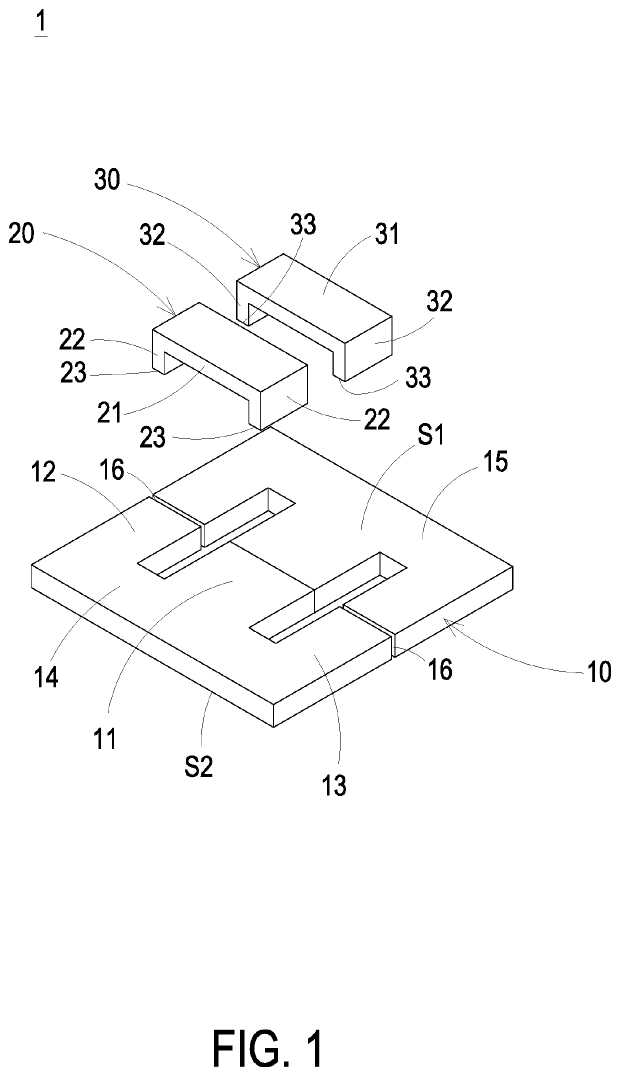
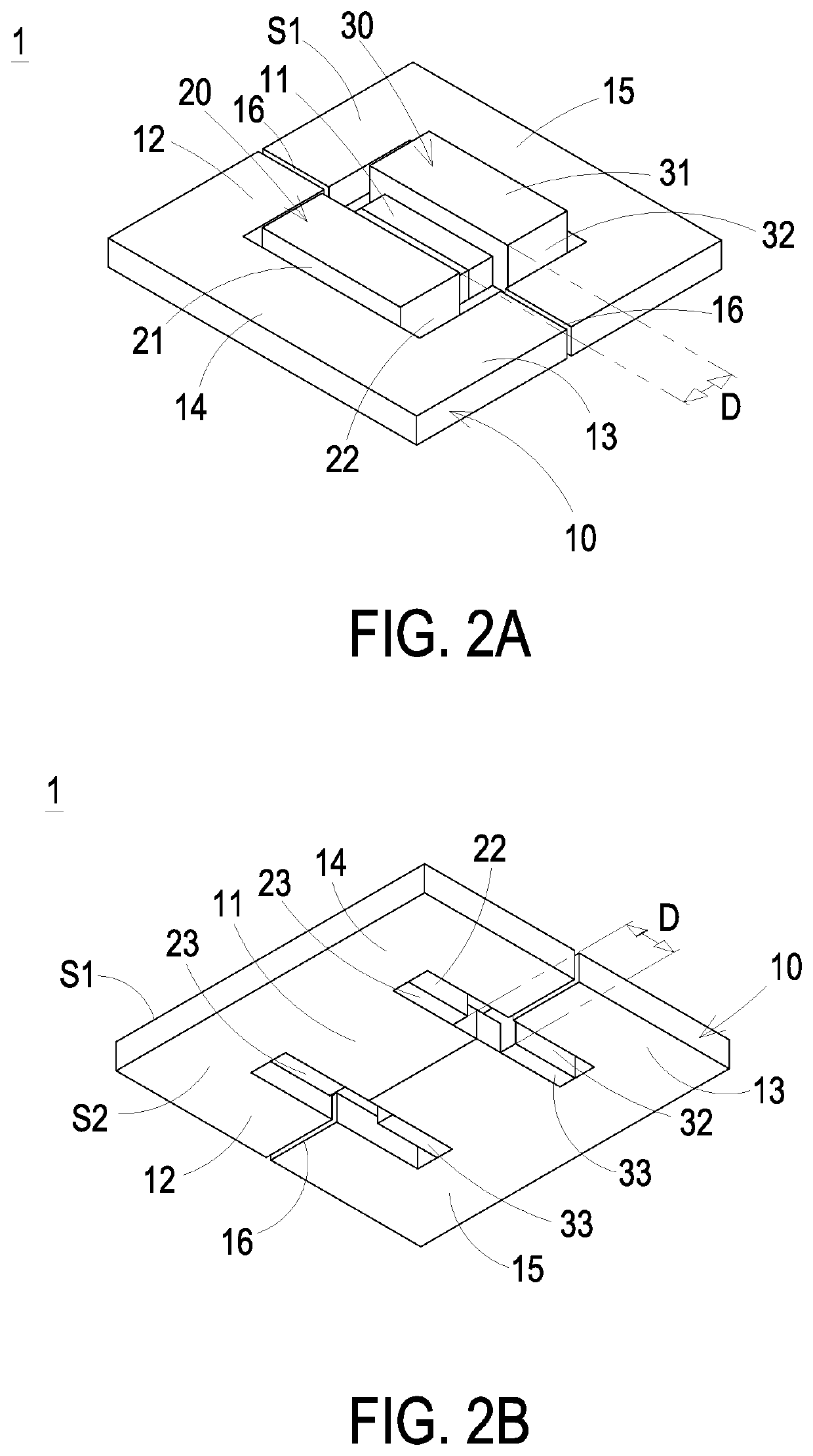
[0064]FIG. 1 is an exploded view illustrating a magnetic component according to the present disclosure. FIGS. 2A and 2B are schematic views illustrating the assembled magnetic component of FIG. 1. As shown in FIG. 1 and FIGS. 2A to 2B, the magnetic component 1 includes a magnetic core 10, a first winding set 20 and a second winding set 30. The magnetic core 10 includes a first magnetic column 11, a second magnetic column 12, a third magnetic column 13, a first connecting portion 14 and a second connecting portion 15, which are connected with each other and form at least one air gap 16, a first side S1 and a second side S2. The first side S1 and the second side S2 are opposite to each other. In the embodiment, the first connecting portion 14 and the second connecting portion 15 are connected with each other through the first magnetic column 11, the second magnetic column 12 and the third magnetic column 13. Moreover, the first magnetic column 11 is located between the second magnetic...

second embodiment

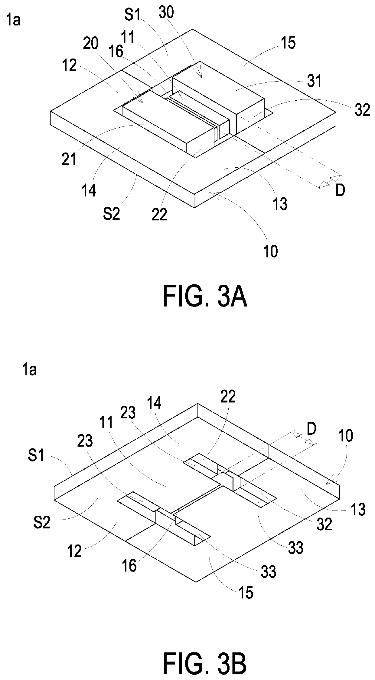
[0066]FIGS. 3A and 3B are schematic views illustrating a magnetic component according to the present disclosure. In the embodiment, the structures, elements and functions of the magnetic component 1a are similar to those of the magnetic component 1 in FIGS. 1 and 2A to 2B, and are not redundantly described herein. In the embodiment, the magnetic core 10 includes a first air gap 16 located at the central position of the first magnetic column 11. The first winding set 20 and the second winding set 30 are located at two ends of the first magnetic column 11. The first winding set 20 and the second winding set 30 are free of overlapping the first air gap 16. Consequently, the first winding set 20 and the second winding set 30 are disposed closely on the first magnetic column 11. It is beneficial to reduce the overall height of the inductor. In addition, comparing with the magnetic component 1 having the first air gaps 16 disposed on the second magnetic column 12 and the third magnetic co...

third embodiment

[0067]FIG. 4 is an exploded view illustrating a magnetic component according to the present disclosure. FIGS. 5A and 5B are schematic views illustrating the assembled magnetic component of FIG. 4. In the embodiment, the structures, elements and functions of the magnetic component 1b are similar to those of the magnetic component 1a in FIGS. 3A and 3B, and are not redundantly described herein. In the embodiment, the thickness of the first magnetic column 11 is thinner than the thickness of the second magnetic column 12 and the thickness of the third magnetic column 13, and / or the thicknesses of the connecting portions 14 and 15. Thus, it is advantageous for the magnetic component 1b to further improve space utilization and reduce the entire height or the occupied area. In addition, the first horizontal portion 21 of the first winding set 20, the second horizontal portion 31 of the second winding set 30, the first connecting portion 14 and the second connecting portion 15 are coplanar...


PUM

PropertyMeasurementUnit
thicknessaaaaaaaaaa
heightaaaaaaaaaa
saturation magnetic flux densityaaaaaaaaaa

Abstract

A magnetic component and a power module using the same are provided. The magnetic component includes a magnetic core, a first winding set and a second winding set. The magnetic core includes two connecting portions connected through three magnetic columns to form two opposite sides. Each connecting portion includes a pair of first air gaps spaced apart by the middle magnetic column. The first winding set and the second winding set are made by a flat conductive body, respectively, and spaced apart at a distance. The first winding set includes two first conducting portions connected through a first horizontal portion. The second winding set includes two second conducting portions connected through a second horizontal portion. The first horizontal portion and the second horizontal portion are exposed to the first side, and the two first conducting portions and the two second conducting portions are extended to the second side.

Description

CROSS-REFERENCE TO RELATED APPLICATION[0001]This application claims priorities to China Patent Application No. 201910628129.X filed on Jul. 12, 2019 and No. 201910013480.8 filed on Jan. 7, 2019. This application is a continuation-in-part application of U.S. application Ser. No. 16 / 259,721 filed on Jan. 28, 2019, and entitled “MAGNETIC COMPONENT AND MANUFACTURING METHOD THEREOF”, which is a continuation-in-part application of U.S. application Ser. No. 15 / 920,548 filed on Mar. 14, 2018, and entitled “POWER MODULE AND MAGNETIC COMPONENT THEREOF”, which is a continuation-in-part application of U.S. application Ser. No. 15 / 784,864 filed on Oct. 16, 2017, and entitled “COUPLED-INDUCTOR MODULE AND VOLTAGE REGULATING MODULE COMPRISING THE SAME”. The entire contents of the above-mentioned patent applications are incorporated herein by reference for all purposes.FIELD OF THE INVENTION[0002]The present disclosure relates to a magnetic component, and more particularly to a magnetic component wi...

Claims


Application Information

Patent Timeline
Patent Type & Authority Applications(United States)
IPC IPC(8): H01F27/28H01F27/24H01F27/29
CPCH01F27/24H01F27/29H01F27/2823H01F27/2804H01F3/14H01F17/04H01F27/2852
Inventor ZHOU, JINPINGZHANG, MINGZHUN
Owner DELTA ELECTRONICS SHANGHAI CO LTD
Why Eureka
Try Eureka